
Rationale and Objectives
The stenosis degree of carotid artery (CA) can be a critical factor for treatment of cerebrovascular disease and for determining candidate of carotid endarterectomy. Currently, three different measuring methods are applied only on projectional cervical images. These measurement methods introduce several demerits such as a thromboembolic event, and three reference positions provide the different measurement results even on same subject. In addition, projection image could not provide the most severe stenosis position by nature; and the manual measurements also provide the inter-observer and intra-observer variability. Therefore, a computerized measuring scheme is necessary to overcome these drawbacks.
Materials and Methods
By applying local adaptive thresholding technique on cervical magnetic resonance angiogram image sequence, CA objects are initially identified. These are used to determine the three-dimensional central axis of CA by using circumscribed quadrangle. The oblique slices are reformatted into two-dimensional image planes, which are perpendicular to the central axis of CA, to provide the circular shape of blood vessel provided that the artery runs horizontally across the scanning axis. After that, region growing technique is applied on obliquely reformatted image sequence followed by geometrically restoration of segmented CA objects.
Results
The percentage of stenosis can be defined by the area ratio of segmented CA to restored CA object. The stenosis grading of is [(A−B)/A]×100% [
(
A
−
B
)
/
A
]
×
100
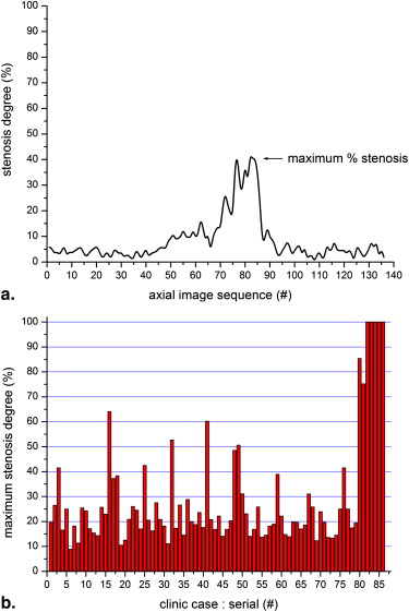
% , where A represents area measure of restored object, B represents area measure of segmented CA object. Experiments have been conducted on both phantom that simulated the mild (30%), moderate (50%), and severe (70%) stenosis degree for validation of proposed measurement approach and 86 carotid arteries from 43 clinical data sets (including 5 occlusion cases).
Conclusions
The automated approach is recommended to measure the carotid stenosis by using axial image sequence. This technique is not only accurate as possible but also robust, simple to handle, and less time consuming as compared to manual measurements. In addition, a computerized carotid stenosis measuring method is necessary to overcome the drawbacks introduced by using the projectional image and measurement variability of inter-observer, intra-observer.
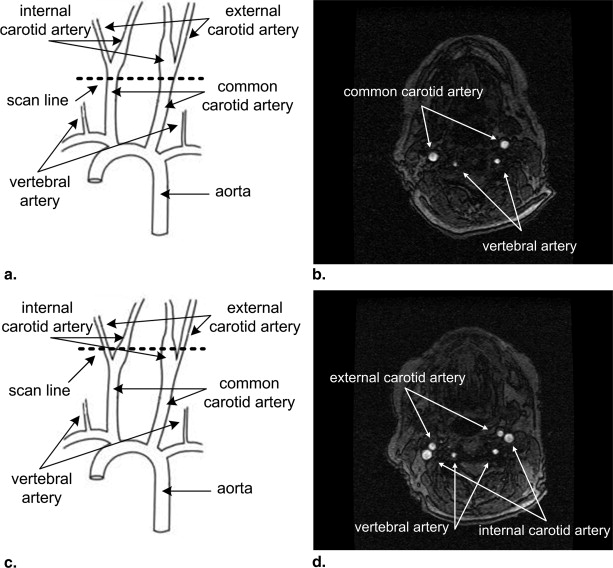
Stroke is the third leading cause of death and a principal cause of severe, long-term disability in much of the industrialized world . A stroke occurs when a blood vessel that brings oxygen and nutrients to the brain bursts or is clogged by a blood clot or some other mass. Because of this rupture or blockage, part of the brain does not get the blood and oxygen it needs. The carotid arteries, which mainly carry blood to the brain, are located on the left and right sides of the front neck. The stenosis occurs when the carotid artery (CA) becomes clogged with fatty deposits. Fatty deposits can narrow the artery so severely that not enough blood can get through to the brain. In addition, pieces of the atherosclerosis may break off and travel with the flowing blood to the brain. These may block small blood vessels and cause the brain infarction. Either way, a stroke could occur. For the purpose of stroke treatment caused by carotid stenosis, carotid angioplasty involves using a balloon catheter to flatten plaque blockage against the artery wall, whereas endarterectomy is the surgical procedure to remove fatty plaque from cervical arteries. Carotid endarterectomy surgery is a treatment that has been proven safe and effective in providing long-term benefits to patients.
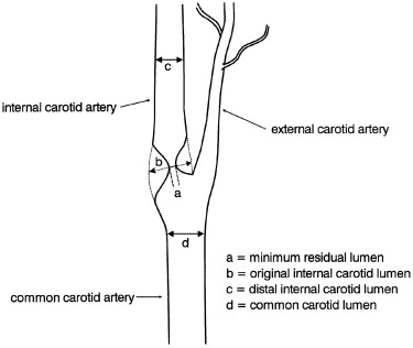
The North American Symptomatic Carotid Endarterectomy Trial (NASCET) provided a method to measure the carotid stenosis using the distal internal CA (ICA) diameter as the reference diameter, and recommended that carotid endarterectomy be performed in symptomatic patients with stenosis of 70% or greater . The European Carotid Surgery Trial (ECST) provided a method to measure the carotid stenosis using the approximate diameter of the carotid bulb as the reference diameter and recommended that carotid endarterectomy should be performed in symptomatic patients with stenosis of 80% or greater . Another method was developed to measure the carotid stenosis based on the measurement of the common carotid (CC) lumen diameter as the reference diameter .
Get Radiology Tree app to read full this article<
Get Radiology Tree app to read full this article<
Materials and methods
Get Radiology Tree app to read full this article<
Image Segmentation
Get Radiology Tree app to read full this article<
Get Radiology Tree app to read full this article<
Determine Central Axis of Carotid Artery
Get Radiology Tree app to read full this article<
Get Radiology Tree app to read full this article<
Oblique Slice Reformation
Get Radiology Tree app to read full this article<
Ax+By+Cz+D=0 A
x
+
B
y
+
C
z
+
D
=
0
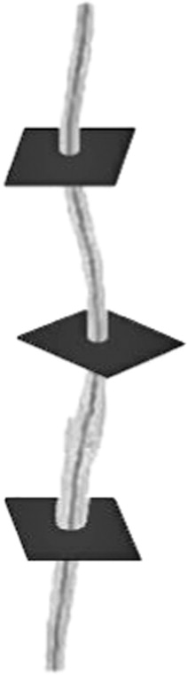
If A = B = 0 , the plane is parallel to the xy -plane as axial slice image. If B = C = 0 , the plane is parallel to the yz-plane as sagittal slice image. If A = C = 0 , the plane is parallel to the xz-plane as coronal slice image. However, oblique slice images are defined as planes that are perpendicular to the arbitrary defined lines connecting the two coordinates in image volume space by applying the equation (1) . Suppose points Pn(xn,yn,zn) P
n
(
x
n
,
y
n
,
z
n
) and Pn+1(xn+1,yn+1,zn+1) P
n
+
1
(
x
n
+
1
,
y
n
+
1
,
z
n
+
1
) are two consecutive central coordinates based on circumscribed quadrangle of segmented CA, and then L is a line in a image volume space that passes through two given points Pn P
n and Pn+1 P
n
+
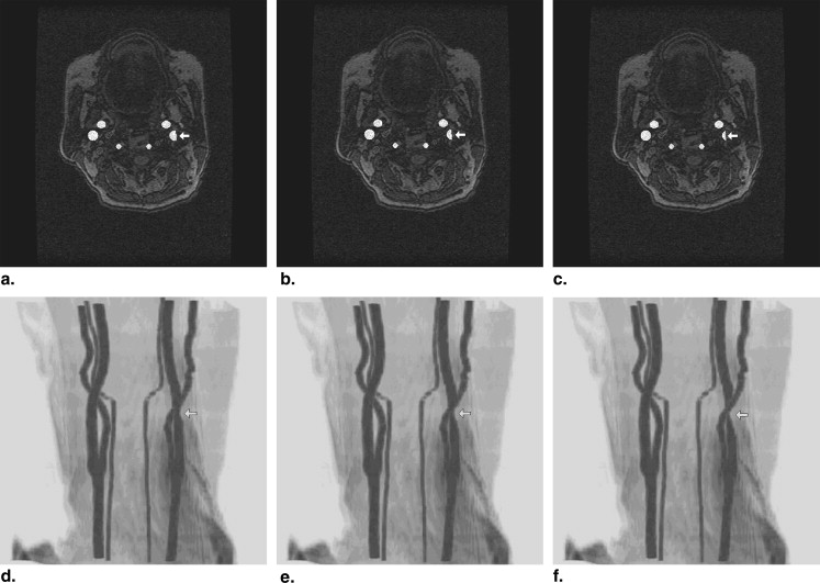
1 ; and which is one of the line segment from central axis of CA object. Then the oblique slice image can be obtained by locating the tangent plane with normal line L in the image volume space. Figure 3 shows the oblique slice images on the central axis of CA object.
Get Radiology Tree app to read full this article<
Region Growing on Obliquely Reformatted Image Sequence
Get Radiology Tree app to read full this article<
Get Radiology Tree app to read full this article<
Get Radiology Tree app to read full this article<
CAs⊂fsandCAu⊂fu C
A
s
⊂
f
s
and
C
A
u
⊂
f
u
RGSc=CAsICAu={(x,y)|(x,y)∈CAsand(x,y)∈CAu} R
G
S
c
=
C
A
s
I
C
A
u
=
{
(
x
,
y
)
|
(
x
,
y
)
∈
C
A
s
and
(
x
,
y
)
∈
C
A
u
}
where RGSc R
G
S
c represents the set of candidate pixel for region growing seed; CAs(x,y) C
A
s
(
x
,
y
) represents the segmented CA area that is the proper subset of fs(x,y) f
s
(
x
,
y
) ; and CAu(x,y) C
A
u
(
x
,
y
) represents the unsegmented CA area that is the proper subset of fu(x,y) f
u
(
x
,
y
) .
Get Radiology Tree app to read full this article<
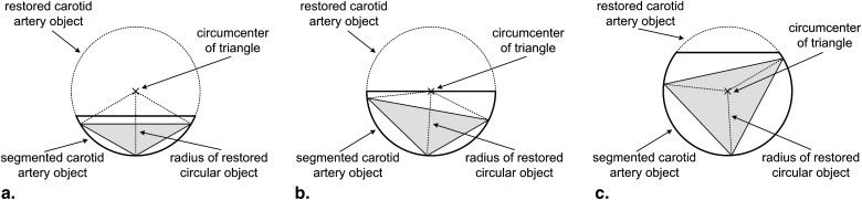
Geometric Restoration
Get Radiology Tree app to read full this article<
Get Radiology Tree app to read full this article<
Get Radiology Tree app to read full this article<
Get Radiology Tree app to read full this article<
Results
Stenosis Measurement
Get Radiology Tree app to read full this article<
[(A−B)/A]×100% [
(
A
−
B
)
/
A
]
×
100
%
where A represents area measure of restored CA object and B represents area measure of segmented CA object. This formula is applied to all axial images from the MRA cervical image sequence; and the stenosis grade is provided as a percentage for each axial image. The percentage of maximum ICA stenosis degree can be determined from each individual stenosis grade of axial image sequence; these can provide the specific location of maximum ICA stenosis.
Get Radiology Tree app to read full this article<
Experiment with Simulated Stenosis on Phantom
Get Radiology Tree app to read full this article<
Get Radiology Tree app to read full this article<
Clinical Data Sets
Get Radiology Tree app to read full this article<
Get Radiology Tree app to read full this article<
Discussion
Get Radiology Tree app to read full this article<
Get Radiology Tree app to read full this article<
References
1. Biller J., Thies W.H.: When to operate in carotid artery disease. Am Family Phys 2000; 61: pp. 400-410.
2. North American Symptomatic Carotid Endarterectomy Trial Collaborators: Beneficial effects of carotid endarterectomy in symptomatic patients with high-grade carotid stenosis. New Engl J Med 1991; 32: pp. 445-453.
3. European Carotid Surgery Trialists’ Collaborative Group: Randomised trial of endarterectomy for recently symptomatic carotid stenosis: final results of the MRC European Carotid Surgery Trial (ECST). Lancet 1998; 351: pp. 1379-1387.
4. Rothwell P.M., Gibson R.J., Slattery J., et. al.: Prognostic value and reproducibility of measurements of carotid stenosis: a comparison of three methods on 1001 angiograms. Stroke 1994; 25: pp. 2440-2444.
5. Hessel S.J., Adams D.F., Abrams H.L.: Complications of angiography. Radiology 1981; 138: pp. 273-281.
6. Rothwell P.M., Gibson R.J., Slattery J., et. al.: Equivalence of measurements of carotid stenosis: a comparison of three methods on 1001 angiograms. European Carotid Surgery Trialists’s Group. Stroke 1994; 25: pp. 2435-2439.
7. Thomas G.B., Finney R.L.: Calculus and Analytic Geometry.1996.Addison-WesleyBoston, MA p. 822–828
8. Kim D.Y., Park J.W.: Computer aided detection of kidney tumor on abdominal computed tomography scans. Acta Radiol 2004; 45: pp. 791-795.
9. Kim D.Y., Chung S.M., Park J.W.: Automatic navigation path generation based on two-phase adaptive region growing algorithm for virtual angioscopy. Med Engineer Phys 2006; 28: pp. 339-347.
10. Kim D.Y., Park J.W.: Multiple-phase segmentation approach for blood vessel extraction on cervical MRA image sequence. Magn Reson Imaging 2009; 27: pp. 256-263.
11. Young G.R., Humphrey P.R.D., Nixon T.E., et. al.: Variability in measurement of extracranial internal carotid artery stenosis as displayed by both digital subtraction and magnetic resonance angiography. Stroke 1996; 27: pp. 467-473.
12. Kim D.Y., Park J.W.: Internal carotid artery stenosis measurements from 3D reconstructed multi-directional views using phantom data sets on MRA image sequence. Eur J Radiol 2009; 72: pp. 65-74.
13. Elgersma O.E.H., Buijs P.C., Wust A.F.J., et. al.: Maximum internal carotid arterial stenosis: assessment with rotational angiography versus conventional intraarterial digital subtraction angiography. Radiology 1999; 213: pp. 777-783.
14. Leclerc X., Godefroy O., Lucas C., et. al.: Internal carotid arterial stenosis: CT angiography with volume rendering. Radiology 1999; 210: pp. 673-682.
15. Kim DY, Park JW. Geometric modeling of cervical artery and phantom implementation on tomographic image sequence. J Visual Commun Image Representation. In press.
16. Lorensen W., Cline H.: Marching cubes: a high resolution 3D surface construction algorithm. Proc ACM SIGGRAPH 1997; pp. 163-169.
17. Leclerc X., Godefroy O., Pruvo J.P., et. al.: Computed tomographic angiography for the evaluation of carotid artery stenosis. Stroke 1995; 26: pp. 1577-1581.
18. Marcus C.D., Ladam-Marcus V.J., Bigot J.L., et. al.: Carotid arterial stenosis: evaluation at CT angiography with the volume rendering technique. Radiology 1999; 211: pp. 775-780.
19. Elgersma O.E.H., Buijs P.C., Wust A.F.J., et. al.: Multidirectional depiction of internal carotid arterial stenosis: three-dimensional time-of-flight MR angiography versus rotational and conventional digital subtraction angiography. Radiology 2000; 216: pp. 511-516.
20. Huston J., Fain S.B., Wald J.T., et. al.: Carotid artery: elliptic centric contrast-enhanced MR angiography compare with conventional angiography. Radiology 2001; 218: pp. 138-143.
21. Rasanen H.T., Manninen H.I., Vanninen R.L., et. al.: Mild carotid artery atherosclerosis: assessment by 3-dimensional time-of-flight magnetic resonance angiography. Stroke 1999; 30: pp. 827-833.
22. Bladin C.F., Alexandrov A.V., Murphy J., et. al.: Carotid stenosis index: a new method of measuring internal carotid artery stenosis. Stroke 1995; 26: pp. 230-234.
23. Mintz B.L., Hobson R.W.: Diagnosis and treatment of carotid artery stenosis. J Amer Osteopath Assoc 2000; 100: pp. s22-s26.
24. Kim D.Y., Park J.W.: Computerized quantification of carotid artery stenosis using MRA axial images. Magnet Reson Imaging 2004; 22: pp. 353-359.
25. Kim D.Y., Park J.W.: Connectivity-based local adaptive thresholding for carotid artery segmentation using MRA images. Image Vision Comp 2005; 23: pp. 1277-1287.