
Standard analog mammography is a screening success story with the proven capacity to reduce mortality from breast cancer . Conventional full-field digital mammography (FFDM) has improved the ability to detect breast cancer in select patient populations . Unfortunately, the accuracy of both analog and digital mammography remains low, with sensitivities reported at 36%–70% depending on breast tissue density and recall rates for many practitioners remaining well above the 5%–10% target range .
A fundamental reason for missed breast cancer is overlapping breast tissue, which can conceal or obscure important features of malignancy . Overlapping tissue is also a frequent cause of false-positive findings which require additional imaging, radiation exposure, expense, and anxiety for patients without added health benefit . Breast tomosynthesis is a new imaging technique designed to eliminate the issue of overlapping tissue. This new technique has the potential to reduce false positive exams while maintaining equal, or possibly improved, sensitivity for detecting breast cancer.
Development of digital tomosynthesis
Digital tomosynthesis uses conventional x-rays and a digital detector to create tomographic cross-sectional images or “slices” of a volume of tissue. These slices are typically thin, with only a 1-mm thick plane of tissue in sharp focus; tissue above and below this plane is out of focus. These thin slices largely eliminate the issue of confusing overlapping tissue often evident on conventional projection mammography and may therefore improve the accuracy of breast imaging.
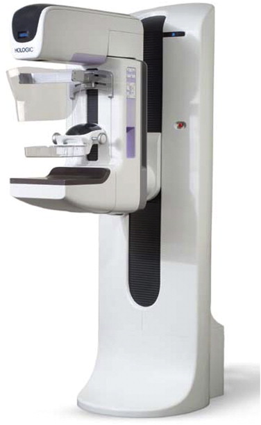
In contrast to conventional mammography, the tube head of a tomosynthesis system is engineered to move in an arc over the breast, while numerous low-dose projection images are obtained ( Fig 1 ). Data from these low-dose projection images are then manipulated using reconstruction algorithms similar to computed tomography (CT) scans to produce thin-slice cross-sectional images through the breast . Because the system is a modified digital mammography unit ( Fig 2 ), tomosynthesis images can be obtained in any orientation that can be obtained with conventional mammography including craniocaudal (CC), mediolateral oblique (MLO), and true lateral orientations.
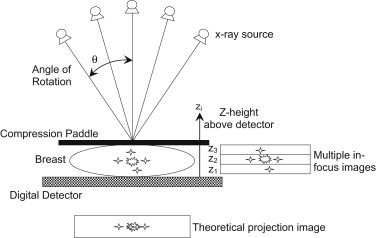
Each of the cross-sectional slices created in digital tomosynthesis is parallel to and at different heights above the detector like conventional tomography . Conventional geometric tomography creates a single in-focus image by moving the x-ray tube and detector in synchrony about the patient, with the in-focus plane determined by the fulcrum of motion . A conventional tomography exam requires a separate acquisition—and, therefore, a separate exposure to ionizing radiation—for each in-focus plane. In contrast, digital tomosynthesis produces tomographic “slices” of an entire tissue volume using a single acquisition and single radiation exposure. The radiation dose for a tomosynthesis exam is therefore similar to that for a single conventional mammographic image .
Get Radiology Tree app to read full this article<
Technical features of digital tomosynthesis
Get Radiology Tree app to read full this article<
Get Radiology Tree app to read full this article<
Table 1
Technical Specifications for Several Breast Tomosynthesis Systems
GE Hologic Selenia Dimensions Siemens MAMMOMAT Inspiration Target/filter Rh/Rh W/Al W/Rh Detector CsI /a-Si a-Se a-Se Pixel pitch (μm) 100 140 (70 μm @ 2× binning) 85 Acquisition time (seconds) 7 4 25 Scan angle (degrees) 25 15 45 Scan motion Step and shoot Continuous Continuous Number of projection images 9 15 25 Dose (vs. full-field digital mammography) 100% 120% 100-200% Reconstruction Simultaneous algebraic reconstruction technique Filtered backprojection Filtered backprojection Reconstructed slice thickness (mm) 0.5-1 1 1
Get Radiology Tree app to read full this article<
Get Radiology Tree app to read full this article<
Get Radiology Tree app to read full this article<
Get Radiology Tree app to read full this article<
Digital Detectors
Get Radiology Tree app to read full this article<
Reconstruction Algorithms
Get Radiology Tree app to read full this article<
Digital Storage Requirements
Get Radiology Tree app to read full this article<
Compression
Get Radiology Tree app to read full this article<
Computer-aided Detection
Get Radiology Tree app to read full this article<
Multimodality Approach
Get Radiology Tree app to read full this article<
Imaging overview
Get Radiology Tree app to read full this article<
Get Radiology Tree app to read full this article<
Normal Anatomy
Get Radiology Tree app to read full this article<
Get Radiology Tree app to read full this article<
Artifacts
Get Radiology Tree app to read full this article<
Get Radiology Tree app to read full this article<
Benign breast lesions
False-positive Mammogram
Get Radiology Tree app to read full this article<
Get Radiology Tree app to read full this article<
Cyst/Fibroadenoma
Get Radiology Tree app to read full this article<
Get Radiology Tree app to read full this article<
Malignant breast lesions
Get Radiology Tree app to read full this article<
Get Radiology Tree app to read full this article<
Calcifications
Get Radiology Tree app to read full this article<
Get Radiology Tree app to read full this article<
Challenges to clinical adoption of tomosynthesis
Get Radiology Tree app to read full this article<
One- versus Two-view Technique
Get Radiology Tree app to read full this article<
Get Radiology Tree app to read full this article<
Get Radiology Tree app to read full this article<
Radiation Dose
Get Radiology Tree app to read full this article<
Get Radiology Tree app to read full this article<
Interpretation Time
Get Radiology Tree app to read full this article<
Get Radiology Tree app to read full this article<
Get Radiology Tree app to read full this article<
Calcifications
Get Radiology Tree app to read full this article<
Get Radiology Tree app to read full this article<
Get Radiology Tree app to read full this article<
Get Radiology Tree app to read full this article<
Get Radiology Tree app to read full this article<
Screening versus Diagnostic
Get Radiology Tree app to read full this article<
Get Radiology Tree app to read full this article<
Get Radiology Tree app to read full this article<
Get Radiology Tree app to read full this article<
Get Radiology Tree app to read full this article<
Get Radiology Tree app to read full this article<
Get Radiology Tree app to read full this article<
Get Radiology Tree app to read full this article<
Imaging Protocol
Get Radiology Tree app to read full this article<
Get Radiology Tree app to read full this article<
Get Radiology Tree app to read full this article<
Other Barriers to Implementation
Get Radiology Tree app to read full this article<
Get Radiology Tree app to read full this article<
Get Radiology Tree app to read full this article<
Get Radiology Tree app to read full this article<
Conclusions
Get Radiology Tree app to read full this article<
References
1. Pisano E.D., Gatsonis C., Hendrick E., et. al.: Diagnostic performance of digital versus film mammography for breast-cancer screening. N Engl J Med 2005; 353: pp. 1773-1783.
2. Vernacchia F.S., Pena Z.G.: Digital mammography: its impact on recall rates and cancer detection rates in a small community-based radiology practice. AJR Am J Roentgenol 2009; 193: pp. 582-585.
3. Lewin J.M., Hendrick R.E., D’Orsi C.J., et. al.: Comparison of full-field digital mammography with screen-film mammography for cancer detection: results of 4,945 paired examinations. Radiology 2001; 218: pp. 873-880.
4. Rosenberg R.D., Yankaskas B.C., Abraham L.A., et. al.: Performance benchmarks for screening mammography. Radiology 2006; 241: pp. 55-66.
5. Holland R., Mravunac M., Hendriks J.H., et. al.: So-called interval cancers of the breast. Pathologic and radiologic analysis of sixty-four cases. Cancer 1982; 49: pp. 2527-2533.
6. Martin J.E., Moskowitz M., Milbrath J.R.: Breast cancer missed by mammography. AJR Am J Roentgenol 1979; 132: pp. 737-739.
7. Feig S.A., Shaber G.S., Patchefsky A., et. al.: Analysis of clinically occult and mammographically occult breast tumors. AJR Am J Roentgenol 1977; 128: pp. 403-408.
8. Bird R.E., Wallace T.W., Yankaskas B.C.: Analysis of cancers missed at screening mammography. Radiology 1992; 184: pp. 613-617.
9. Rafferty E.A.: Digital mammography: novel applications. Radiol Clin N Am 2007; 45: pp. 831-843.
10. Bick U., Diekmann F.: Digital mammography.2010.SpringerBerlin
11. Niklason L.T., Christian B.T., Niklason L.E., et. al.: Digital tomosynthesis in breast imaging. Radiology 1997; 205: pp. 399-406.
12. Dobbins J.T., Godfrey D.J.: Digital x-ray tomosynthesis: current state of the art and clinical potential. Phys Med Biol 2003; 48: pp. R65-R106.
13. Littleton J.T.: Tomography: physical principles and clinical applications.1976.Williams & WilkinsBaltimore
14. Poplack S.P., Tosteson T.D., Kogel C.A., et. al.: Digital breast tomosynthesis: initial experience in 98 women with abnormal digital screening mammography. AJR Am J Roentgenol 2007; 189: pp. 616-623.
15. Dobbins J.T.: Tomosynthesis imaging: at a translational crossroads. Med Phys 2009; 36: pp. 1956-1967.
16. Siedses Des Plantes B.G.: Eine neue methode zur differenzierung in der roentgenographie (planigraphie). Acta Radiol 1932; 13: pp. 182-192.
17. Grant D.G.: Tomosynthesis: a three-dimensional radiographic imaging technique. IEEE Trans Biomed Eng 1972; 19: pp. 20-28.
18. Svane G, Azavedo E, Lindman K, et al. Clinical experience of photon counting breast tomosynthesis: comparison with traditional mammography. Acta Radiol 2011; 52:134–142.
19. Aslund M., Cederstrom B., Lundqvist M., et. al.: Physical characterization of a scanning photon counting digital mammography system based on Si-strip detectors. Med Phys 2007; 34: pp. 1918-1925.
20. Qian X., Rajaram R., Calderon-Colon X., et. al.: Design and characterization of a spatially distributed multibeam field emission x-ray source for stationary digital breast tomosynthesis. Med Phys 2009; 36: pp. 4389-4399.
21. Sprenger F., Calderon X., Gidcumb E., et. al.: Stationary digital breast tomosynthesis with distributed field emission x-ray tube. Proc SPIE 2011; pp. 7961.
22. Shaheen E., Marshall N.W., Bosmans H.: Investigation of the effect of tube motion in breast tomosynthesis: Continuous or step and shoot?. SPIE Med Imaging 2011; pp. 12-13.
23. Suryanarayanan S., Karellas A., Vedantham S., et. al.: Comparison of tomosynthesis methods used with digital mammography. Acad Radiol 2000; 7: pp. 1085-1097.
24. Wu T., Moore R.H., Rafferty E.A., et. al.: A comparison of reconstruction algorithms for breast tomosynthesis. Med Phys 2004; 31: pp. 2636-2647.
25. Zhang Y., Chan H.P., Sahiner B., et. al.: A comparative study of limited-angle cone-beam reconstruction methods for breast tomosynthesis. Med Phys 2006; 33: pp. 3781-3795.
26. Helvie MA. Digital mammography imaging: breast tomosynthesis and advanced applications. Radiol Clin N Am 2010; 48:917–929.
27. Thompson J., Chen B., Richard S., et. al.: Wide-angle breast tomosynthesis: initial comparative evaluation. SPIE Med Imaging 2010; 4:
28. Richard S, Samei E. Quantitative breast tomosynthesis: from detectability to estimability. Med Phys 2010; 37:6157–6165.
29. Richard S, Samei E. Quantitative imaging in breast tomosynthesis and CT: comparison of detection and estimation task performance. Med Phys 2010; 37:2627–2637.
30. Chawla A.S., Lo J.Y., Baker J.A., et. al.: Optimized image acquisition for breast tomosynthesis in projection and reconstruction space. Med Phys 2009; 36: pp. 4859-4869.
31. Das M., Gifford H.C., O’Connor J.M., et. al.: Evaluation of a variable dose acquisition technique for microcalcification and mass detection in digital breast tomosynthesis. Med Phys 2009; 36: pp. 1976-1984.
32. Sechopoulos I., Ghetti C.: Optimization of the acquisition geometry in digital tomosynthesis of the breast. Med Phys 2009; 36: pp. 1199-1207.
33. Reiser I., Nishikawa R.M.: Task-based assessment of breast tomosynthesis: effect of acquisition parameters and quantum noise. Med Phys 2010; 37: pp. 1591-1600.
34. Sidky E.Y., Pan X., Reiser I.S., et. al.: Enhanced imaging of microcalcifications in digital breast tomosynthesis through improved image-reconstruction algorithms. Med Phys 2009; 36: pp. 4920-4932.
35. Zhang Y., Chan H.P., Sahiner B., et. al.: Application of boundary detection information in breast tomosynthesis reconstruction. Med Phys 2007; 34: pp. 3603-3613.
36. Hu Y.H., Zhao B., Zhao W.: Image artifacts in digital breast tomosynthesis: investigation of the effects of system geometry and reconstruction parameters using a linear system approach. Med Phys 2008; 35: pp. 5242-5252.
37. Zhang Y., Chan H.P., Sahiner B., et. al.: Artifact reduction methods for truncated projections in iterative breast tomosynthesis reconstruction. J Comput Assist Tomogr 2009; 33: pp. 426-435.
38. Förnvik D., Jerebko A.K., Timberg P.A.S., et. al.: A human observer study for evaluation and optimization of reconstruction methods in breast tomosynthesis using clinical cases. SPIE Med Imaging 2011; 45:
39. Jerebko A.K., Mertelmeier T.: Evaluation and optimization of the maximum likelihood and iterative FBP approaches for image reconstruction in digital breast tomosynthesis. SPIE Med Imaging 2010; pp. 4-5.
40. Saunders R.S., Samei E., Lo J.Y., et. al.: Can compression be reduced for breast tomosynthesis? Monte Carlo study on mass and microcalcification conspicuity in tomosynthesis. Radiology 2009; 251: pp. 673-682.
41. Fornvik D, Andersson I, Svahn T, et al. The effect of reduced breast compression in breast tomosynthesis: human observer study using clinical cases. Radiat Prot Dosim 2010; 139:118–123.
42. Reiser I., Nishikawa R.M., Edwards A.V., et. al.: Automated detection of microcalcification clusters for digital breast tomosynthesis using projection data only: a preliminary study. Med Phys 2008; 35: pp. 1486-1493.
43. Reiser I., Nishikawa R.M., Giger M.L., et. al.: Computerized mass detection for digital breast tomosynthesis directly from the projection images. Med Phys 2006; 33: pp. 482-491.
44. Chan H.P., Wu Y.T., Sahiner B., et. al.: Characterization of masses in digital breast tomosynthesis: comparison of machine learning in projection views and reconstructed slices. Med Phys 2010; 37: pp. 3576-3586.
45. Chan H.P., Wei J., Zhang Y., et. al.: Computer-aided detection of masses in digital tomosynthesis mammography: comparison of three approaches. Medical physics 2008; 35: pp. 4087-4095.
46. Singh S., Tourassi G.D., Baker J.A., et. al.: Automated breast mass detection in 3D reconstructed tomosynthesis volumes: a featureless approach. Med Phys 2008; 35: pp. 3626-3636.
47. Mazurowski M, Lo JY, Harrawood B, et al. Mutual information-based template matching scheme for detection of breast masses: from mammography to digital breast tomosynthesis. J Biomed Inform. In press.
48. Chan H.-P., Sahiner B., Wei J., et. al.: Nico K.Ronald M.S.Digital breast tomosynthesis: computerized detection of microcalcifications in reconstructed breast volume using a 3D approach.2010.SPIE 76241D
49. Li J., Goodsitt M.M., Padilla F., et. al.: Effect of a gel retainment dam on automated ultrasound coverage in a dual-modality breast imaging system. J Ultrasound Med 2010; 29: pp. 1075-1081.
50. Sinha SP, Roubidoux MA, Helvie MA, et al. Multi-modality 3D breast imaging with X-Ray tomosynthesis and automated ultrasound. Conference proceedings: Annual International Conference of the IEEE Engineering in Medicine and Biology Society. IEEE Engineering in Medicine and Biology Society. Conference 2007; 2007:1335–1338.
51. Williams M.B., Judy P.G., Gunn S., et. al.: Dual-modality breast tomosynthesis. Radiology 2010; 255: pp. 191-198.
52. Fang Q., Selb J., Carp S.A., et. al.: Combined optical and X-ray tomosynthesis breast imaging. Radiology 2011; 258: pp. 89-97.
53. Michaelsen K.E., Krishnaswamy V., Pogue B.W., et. al.: Bruce J.T.Arjun G.Y.Mamoru T.Eva M.S.-M.Robert R.A.Continuous-wave and frequency domain optimization in breast tomosynthesis-guided diffuse spectroscopy.2011.SPIE 78962K
54. Schmitzberger F.F., Fallenberg E.M., Lawaczeck R., et. al.: Development of low-dose photon-counting contrast-enhanced tomosynthesis with spectral imaging. Radiology 2011; 259: pp. 558-564.
55. Carton A.K., Ullberg C., Maidment A.D.: Optimization of a dual-energy contrast-enhanced technique for a photon-counting digital breast tomosynthesis system: II. An experimental validation. Med Phys 2010; 37: pp. 5908-5913.
56. Carton A.K., Ullberg C., Lindman K., et. al.: Optimization of a dual-energy contrast-enhanced technique for a photon-counting digital breast tomosynthesis system: I. A theoretical model. Med Phys 2010; 37: pp. 5896-5907.
57. Carton A.K., Gavenonis S.C., Currivan J.A., et. al.: Dual-energy contrast-enhanced digital breast tomosynthesis—a feasibility study. Br J Radiol 2010; 83: pp. 344-350.
58. Chen S.C., Carton A.K., Albert M., et. al.: Initial clinical experience with contrast-enhanced digital breast tomosynthesis. Acad Radiol 2007; 14: pp. 229-238.
59. Hu Y.-H., Zhao W.: Norbert J.P.Ehsan S.Robert M.N.A 3D linear system model for the optimization of dual-energy contrast-enhanced digital breast tomosynthesis.2011.SPIE 79611C
60. Wu T., Moore R.H., Kopans D.B.: Voting strategy for artifact reduction in digital breast tomosynthesis. Med Phys 2006; 33: pp. 2461-2471.
61. Diekmann F., Meyer H., Diekmann S., et. al.: Thick slices from tomosynthesis data sets: phantom study for the evaluation of different algorithms. J Digit Imaging 2009; 22: pp. 519-526.
62. Rafferty E, Niklason L, L. J-M. Breast tomosynthesis: one view or two? Radiological Society of North American annual meeting. Chicago, IL, 2006.
63. Kopans D., Moore R.: Digital breast tomosynthesis (DBT) NCI 3000-Women Trial.2009.Radiological Society of North AmericaChicago
64. Fornvik D, Zackrisson S, Ljungberg O, et al. Breast tomosynthesis: accuracy of tumor measurement compared with digital mammography and ultrasonography. Acta Radiol 2010; 51:240–247.
65. Bakic P.R., Carton A.K., Kontos D., et. al.: Breast percent density: estimation on digital mammograms and central tomosynthesis projections. Radiology 2009; 252: pp. 40-49.
66. Andersson I., Ikeda D.M., Zackrisson S., et. al.: Breast tomosynthesis and digital mammography: a comparison of breast cancer visibility and BIRADS classification in a population of cancers with subtle mammographic findings. Eur Radiol 2008; 18: pp. 2817-2825.
67. Gennaro G., Toledano A., di Maggio C., et. al.: Digital breast tomosynthesis versus digital mammography: a clinical performance study. Eur Radiol 2009; 20: pp. 1545-1553.
68. Lundgren B.: The oblique view of mammography. Br J Radiol 1977; 50: pp. 626-628.
69. Bassett L.W., Gold R.H.: Breast radiography using the oblique projection. Radiology 1983; 149: pp. 585-587.
70. Chakrabarti K., Ochs R., Pennello G., et. al.: FDA executive summary: meeting of the radiological devices advisory panel.2010.Food and Drug AdministrationGaithersburg, MD
71. Wu T., Stewart A., Stanton M., et. al.: Tomographic mammography using a limited number of low-dose cone-beam projection images. Med Phys 2003; 30: pp. 365-380.
72. Sechopoulos I, Feng SS, D’Orsi CJ. Dosimetric characterization of a dedicated breast computed tomography clinical prototype. Med Phys 2010; 37:4110–4120.
73. Gur D., Abrams G.S., Chough D.M., et. al.: Digital breast tomosynthesis: observer performance study. AJR Am J Roentgenol 2009; 193: pp. 586-591.
74. Hendrick RE. Radiation doses and cancer risks from breast imaging studies. Radiology 257:246–253.
75. Moore R, Avital L, Alexander S, et al. Reading behavior for screening digital breast tomosynthesis (DBT) compared to conventional 2Dmammography (CM). RSNA 2006. Available at: http://rsna2006.rsna.org/rsna2006/v2006/conference/event_display.cfm?am_id=2&em_id=8002013&track=yes .
76. Good W.F., Abrams G.S., Catullo V.J., et. al.: Digital breast tomosynthesis: a pilot observer study. AJR Am J Roentgenol 2008; 190: pp. 865-869.
77. Liang H., Park S., Gallas B.D., et. al.: Image browsing in slow medical liquid crystal displays. Acad Radiol 2008; 15: pp. 370-382.
78. Zhao B., Zhao W.: Imaging performance of an amorphous selenium digital mammography detector in a breast tomosynthesis system. Med Phys 2008; 35: pp. 1978-1987.
79. Bissonnette M., Hansroul M., Masson E., et. al.: Flynn M.J.Digital breast tomosynthesis using an amorphous selenium flat panel detector.2005.SPIE 529–540
80. Lu Y., Chan H.P., Wei J., et. al.: Selective-diffusion regularization for enhancement of microcalcifications in digital breast tomosynthesis reconstruction. Med Phys 2010; 37: pp. 6003-6014.
81. Das M., Gifford H.C., O’Connor J.M., et. al.: Penalized maximum likelihood reconstruction for improved microcalcification detection in breast tomosynthesis. IEEE Trans Med Imaging 2011; 30: pp. 904-914.
82. Spangler ML, Zuley ML, Sumkin JH, et al. Detection and classification of calcifications on digital breast tomosynthesis and 2D digital mammography: a comparison. AJR Am J Roentgenol 2011; 196:320–324.
83. Teertstra H.J., Loo C.E., van den Bosch M.A., et. al.: Breast tomosynthesis in clinical practice: initial results. Eur Radiol 2009; 20: pp. 16-24.
84. Kopans D., Moore R.: Calcification in Digital Breast Tomosynthesis (DBT).2008.Radiological Society of North AmericaChicago
85. Park J.M., Franken E.A., Garg M., et. al.: Breast tomosynthesis: present considerations and future applications. Radiographics 2007; 27: pp. S231-S240.
86. Svahn T, Andersson I, Chakraborty D, et al. The diagnostic accuracy of dual-view digital mammography, single-view breast tomosynthesis and a dual-view combination of breast tomosynthesis and digital mammography in a free-response observer performance study. Radiat Prot Dosim 2010; 139:113–117.
87. Liberman L., Bracero N., Morris E., et. al.: MRI-guided 9-gauge vacuum-assisted breast biopsy: initial clinical experience. AJR Am J Roentgenol 2005; 185: pp. 183-193.
88. Eby P.R., Lehman C.D.: Magnetic resonance imaging–guided breast interventions. Top Magn Reson Imaging 2008; 19: pp. 151-162.
89. Kopans D.B., Rusby J.E.: Cutaneous caves and subcutaneous adipose columns in the breast: radiologic-pathologic correlation. Radiology 2008; 249: pp. 779-784.