
Rationale and Objectives
To evaluate and compare the accuracy of cross-sectional imaging using an intravascular antenna in the context of vascular morphological measurements performed during a magnetic resonance imaging (MRI)-guided vascular intervention.
Materials and Methods
Cross-sectional imaging of a multimodality vascular phantom was performed using intravascular and surface MRI, multidetector computed tomography, and intravascular ultrasound (IVUS). Using a balanced steady-state free-precession sequence, 18 sequences parameters sets were investigated (12 for intravascular MRI and 6 for surface MRI). Vessel diameters for all images and modalities were computed using an automated vessel segmentation algorithm.
Results
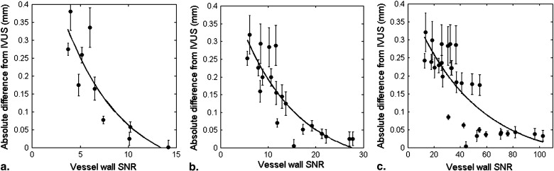
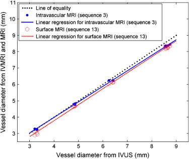
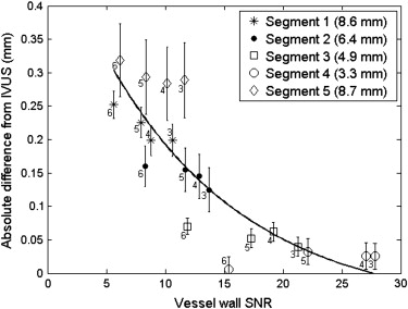
Using IVUS as a gold standard, imaging using an intravascular antenna leads to an increase in geometrical accuracy in comparison to traditional surface MRI. This level of accuracy appears to follow a significant inverse proportionality relation in respect to vessel wall signal-to-noise ratio (SNR). Taking into account the rapid decrease in SNR as a function of the distance to the intravascular antenna, these results imply that, for a given level of geometrical accuracy, faster sequences can be used for the imaging of smaller vessels.
Conclusion
Imaging using an intravascular antenna appears as a valuable assistance to increase the accuracy of vascular morphological measurements. This increase in geometrical accuracy would be beneficial during the realization of an MRI-guided intervention, either to perform pretreatment measurements or to assess the outcome of the procedure. Acquisition parameters should be tailored to vessel size and procedural time constraints.
Atherosclerosis and arterial obstructive diseases are leading causes of death and impairment in Western countries. Imperative to an effective treatment of stenosis is an accurate estimation of the plaque burden and vessel morphology and a prediction of the plaque vulnerability. Because of its excellent soft-tissue contrast and flexibility, magnetic resonance imaging (MRI) is increasingly used to detect and quantify stenosis and image atherosclerotic plaque, especially in superficial vessels such as carotid arteries .
In addition to the established diagnostic use of MRI with surface coils, several developments have been made toward the accomplishment of therapeutic vascular procedures under MRI guidance . In comparison to the standard clinical setup using x-rays, MRI offers a complete elimination of the use of ionizing radiation, a reduction in the use of nephrotoxic contrast agents, functional and anatomical information in three dimensions, and a significantly improved contrast between soft tissues. Several techniques have been proposed for the visualization and tracking of the interventional devices, generally relying on either a passive or an active approach. In a similar scope, active intravascular imaging coils have also been used for atherosclerotic plaque imaging and classification . However, to our knowledge, the benefits arising from the use of an intravascular coil allowing vascular imaging during a therapeutic procedure have not been completely investigated. Still, in such an interventional context, in which important time constraints exist, the higher signal-to-noise ratio (SNR) achievable with intravascular MRI could likely be advantageous to increase the accuracy and precision of morphologic measurements either before a procedure or to assess the therapeutic outcome.
Get Radiology Tree app to read full this article<
Get Radiology Tree app to read full this article<
Materials and methods
Vascular Phantom
Get Radiology Tree app to read full this article<
Intravascular Antenna
Get Radiology Tree app to read full this article<
Imaging Protocols
Get Radiology Tree app to read full this article<
Table 1
Magnetic Resonance Imaging Sequence Parameters
Acquisition Time (seconds/slice) Matrix FoV (mm) In-plane Resolution (μm) Slice Thickness (mm) TR (ms) TE (ms) BW (Hz/pixel) NEX iPAT Intravascular MRI Sequences 1 4.6 192 × 192 32 × 32 167 3 11.84 5.92 199 2 1 2 2.3 192 × 192 32 × 32 167 3 11.84 5.92 199 1 1 3 4.5 128 × 128 32 × 32 250 3 8.81 4.41 266 4 1 4 3.4 128 × 128 32 × 32 250 3 8.81 4.41 266 3 1 5 2.3 128 × 128 32 × 32 250 3 8.81 4.41 266 2 1 6 1.1 128 × 128 32 × 32 250 3 8.81 4.41 266 1 1 7 4.4 64 × 64 32 × 32 500 3 6.79 3.40 266 10 1 8 3.5 64 × 64 32 × 32 500 3 6.79 3.40 266 8 1 9 2.6 64 × 64 32 × 32 500 3 6.79 3.40 266 6 1 10 1.7 64 × 64 32 × 32 500 3 6.79 3.40 266 4 1 11 0.9 64 ×64 32 × 32 500 3 6.79 3.40 266 2 1 12 0.4 64 × 64 32 × 32 500 3 6.79 3.40 266 1 1 Surface MRI Sequences 13 4.1 1024 × 1024 350 × 350 342 3 7.82 3.91 257 1 2 14 4.8 704 × 704 350 × 350 497 3 6.83 3.41 263 1 1 15 2.5 704 × 704 350 × 350 497 3 6.83 3.41 263 1 2 16 4.5 384 × 384 350 × 350 911 3 5.89 2.95 266 2 1 17 2.3 384 × 384 350 × 350 911 3 5.89 2.95 266 1 1 18 1.2 384 × 384 350 × 350 911 3 5.89 2.95 266 1 2
FoV, field of view; TR, repetition time; TE, echo time; BW, bandwidth; NEX, number of excitations; iPAT, parallel imaging (generalized autocalibrating partially parallel acquisitions) acceleration factor.
Get Radiology Tree app to read full this article<
Get Radiology Tree app to read full this article<
Get Radiology Tree app to read full this article<
Diameter Measurement Algorithm
Get Radiology Tree app to read full this article<
Get Radiology Tree app to read full this article<
Get Radiology Tree app to read full this article<
Results
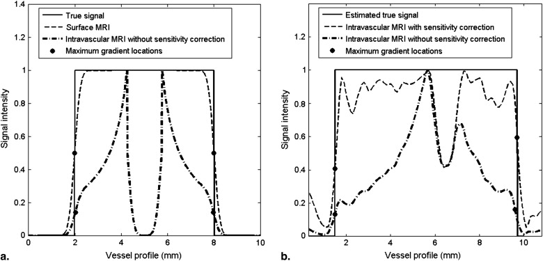
Coil Sensitivity Profile Effects
Get Radiology Tree app to read full this article<
Get Radiology Tree app to read full this article<
Get Radiology Tree app to read full this article<
Geometrical Accuracy Results
Get Radiology Tree app to read full this article<
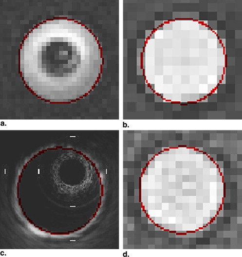
Table 2
Measured Mean Diameter Differences in Comparison to IVUS
Acquisition Time (seconds/slice) In-plane Resolution (μm) Mean Relative Difference to IVUS 95% Confidence Interval Intravascular MRI Sequences 1 4.6 167 -2.2% -2.9% to -1.5% 2 2.3 167 -2.6% -3.3% to -1.9% 3 4.5 250 -1.6% -2.4% to -0.9% 4 3.4 250 -1.8% -2.5% to -1.0% 5 2.3 250 -1.8% -2.6% to -1.0% 6 1.1 250 -2.2% -2.9% to -1.4% 7 4.4 500 -2.0% -2.8% to -1.1% 8 3.5 500 -2.0% -2.8% to -1.1% 9 2.6 500 -1.9% -2.8% to -1.1% 10 1.7 500 -2.0% -2.9% to -1.2% 11 0.9 500 -2.2% -3.0% to -1.4% 12 0.4 500 -2.6% -3.3% to -1.9% Surface MRI Sequences 13 4.1 342 -4.2% -5.1% to -3.3% 14 4.8 497 -4.3% -4.9% to -3.8% 15 2.5 497 -4.6% -5.5% to -3.7% 16 4.5 911 -7.4% -9.0% to -5.8% 17 2.3 911 -7.5% -8.7% to -6.2% 18 1.2 911 -7.7% -9.0% to -6.5% MDCT -1.9% -2.3% to -1.5%
IVUS, intravascular ultrasound; MRI, magnetic resonance imaging; MDCT, multidetector computed tomography.
Get Radiology Tree app to read full this article<
Get Radiology Tree app to read full this article<
Get Radiology Tree app to read full this article<
Get Radiology Tree app to read full this article<
Get Radiology Tree app to read full this article<
Get Radiology Tree app to read full this article<
Get Radiology Tree app to read full this article<
Get Radiology Tree app to read full this article<
Get Radiology Tree app to read full this article<
Discussion
Get Radiology Tree app to read full this article<
Get Radiology Tree app to read full this article<
Get Radiology Tree app to read full this article<
Get Radiology Tree app to read full this article<
Get Radiology Tree app to read full this article<
Acknowledgments
Get Radiology Tree app to read full this article<
Get Radiology Tree app to read full this article<
References
1. Rofsky N.M., Adelman M.A.: MR angiography in the evaluation of atherosclerotic peripheral vascular disease. Radiology 2000; 214: pp. 325-334.
2. Steffens J.C., Schafer F.K.W., Oberscheid B., et. al.: Bolus-chasing contrast-enhanced 3D MRA of the lower extremity: comparison with intraarterial DSA. Acta Radiol 2003; 44: pp. 185-192.
3. Zhang S., Cai J., Luo Y., et. al.: Measurement of carotid wall volume and maximum area with contrast-enhanced 3D MR Imaging: initial observations. Radiology 2003; 228: pp. 200-205.
4. Elgort D.R., Hillenbrand C.M., Zhang S., et. al.: Image-guided and -monitored renal artery stenting using only MRI. J Magnet Reson Imaging 2006; 23: pp. 619-627.
5. Omary R.A., Gehl J.A., Schirf B.E., et. al.: MR imaging- versus conventional X-ray fluoroscopy-guided renal angioplasty in swine: prospective randomized comparison. Radiology 2006; 238: pp. 489-496.
6. Bakker C.J., Hoogeveen R.M., Weber J., et. al.: Visualization of dedicated catheters using fast scanning techniques with potential for MR-guided vascular interventions. Magnet Reson Med 1996; 36: pp. 816-820.
7. Dumoulin C.L., Souza S.P., Darrow R.D.: Real-time position monitoring of invasive devices using magnetic resonance. Magnet Reson Med 1993; 29: pp. 411-415.
8. Larose E., Kinlay S., Selwyn A.P., et. al.: Improved characterization of atherosclerotic plaques by gadolinium contrast during intravascular magnetic resonance imaging of human arteries. Atherosclerosis 2008; 196: pp. 915-925.
9. Rogers W.J., Prichard J.W., Hu Y.L., et. al.: Characterization of signal properties in atherosclerotic plaque components by intravascular MRI. Arterioscler Thromb Vasc Biol 2000; 20: pp. 1824-1830.
10. Omary R.A., Schirf B.E., Green J.D., et. al.: Catheter-directed MR angiography and cross-sectional imaging for the assessment of renal artery stenosis. J Vasc Intervent Radiol 2005; 16: pp. 255-260.
11. Hillenbrand C.M., Jesberger J.A., Wong E.Y., et. al.: Toward rapid high resolution in vivo intravascular MRI: evaluation of vessel wall conspicuity in a porcine model using multiple imaging protocols. J Magnet Reson Imaging 2006; 23: pp. 135-144.
12. Scheffler K., Lehnhardt S.: Principles and applications of balanced SSFP techniques. Eur Radiol 2003; 13: pp. 2409-2418.
13. Nissen S.E., Yock P.: Intravascular ultrasound: novel pathophysiological insights and current clinical applications. Circulation 2001; 103: pp. 604-616.
14. Cloutier G., Soulez G., Qanadli S.D., et. al.: A multimodality vascular imaging phantom with fiducial markers visible in DSA, CTA, MRA, and ultrasound. Med Phys 2004; 31: pp. 1424-1433.
15. Tang A., Cloutier G., Therasse E., et. al.: Optimization of spatial resolution for peripheral magnetic resonance angiography. Acad Radiol 2007; 14: pp. 54-61.
16. Ocali O., Atalar E.: Intravascular magnetic resonance imaging using a loopless catheter antenna. Magnet Reson Med 1997; 37: pp. 112-118.
17. Susil R.C., Yeung C.J., Atalar E.: Intravascular extended sensitivity (IVES) MRI antennas. Magnet Reson Med 2003; 50: pp. 383-390.
18. Griswold M.A., Jakob P.M., Heidemann R.M., et. al.: Generalized autocalibrating partially parallel acquisitions (GRAPPA). Magnet Reson Med 2002; 47: pp. 1202-1210.
19. Boussion N., Soulez G., Guise J.A.D., et. al.: Geometrical accuracy and fusion of multimodal vascular images: a phantom study. Med Phys 2004; 31: pp. 1434-1443.
20. Hurst G.C., Hua J., Duerk J.L., et. al.: Intravascular (catheter) NMR receiver probe: preliminary design analysis and application to canine iliofemoral imaging. Magnet Reson Med 1992; 24: pp. 343-357.
21. Martin A.J., Plewes D.B., Henkelman R.M.: MR imaging of blood vessels with an intravascular coil. J Magnet Reson Med 1992; 2: pp. 421-429.
22. Quick HH, Ladd ME, Zimmermann-Paul GG, et al. Single-loop coil concepts for intravascular magnetic resonance imaging. Magnet Reson Med1999; 41:751–758.
23. Salvado O., Yutzy S.R., Nguyen M.S., et. al.: Characterization of atherosclerosis lesions with TrueFISP intravascular MRI. Proc Int Soc Magnet Reson Med 2007; 15: pp. 3108.
24. Nitz W.R., Oppelt A., Renz W., et. al.: On the heating of linear conductive structures as guide wires and catheters in interventional MRI. J Magnet Reson Med 2001; 13: pp. 105-114.
25. Weiss S., Vernickel P., Schaeffter T., et. al.: Transmission line for improved RF safety of interventional devices. Magnet Reson Med 2005; 54: pp. 182-189.
26. Umathum R., Muller S., Semmler W., et. al.: An actively segmented transmission line for improved MR safety of interventional devices. Proc Int Soc Magnet Reson Med 2006; 14: pp. 1396.
27. Kurpad K.N., Bieging E.T., Unal O.: Improved RF safety of interventional devices using cable traps. Proc Int Soc Magnet Reson Med 2008; 16: pp. 1063.
28. Hillenbrand C.M., Elgort D.R., Wong E.Y., et. al.: Active device tracking and high-resolution intravascular MRI using a novel catheter-based, opposed-solenoid phased array coil. Magnet Reson Med 2004; 51: pp. 668-675.
29. El-Sharkawy A.-M.M., Qian D., Bottomley P.A.: The performance of interventional loopless MRI antennae at higher magnetic field strengths. Med Phys 2008; 35: pp. 1995-2006.
30. Kozerke S., Botnar R., Oyre S., et. al.: Automatic vessel segmentation using active contours in cine phase contrast flow measurements. J Magnet Reson Imaging 1999; 10: pp. 41-51.
31. Hoogeveen R.M., Bakker C.J., Viergever M.A.: Limits to the accuracy of vessel diameter measurements in MR angiography. J Magnet Reson Imaging 1998; 8: pp. 1228-1235.