
Rationale and Objectives
Anatomically realistic biomechanical models of the breast potentially provide a reliable way of mapping tissue locations across medical images, such as mammograms, magnetic resonance imaging (MRI), and ultrasound. This work presents a new modeling framework that enables us to create biomechanical models of the breast that are customized to the individual. We demonstrate the framework’s capabilities by creating models of the left breasts of two volunteers and tracking their deformations across MRIs.
Materials and Methods
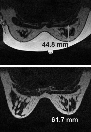
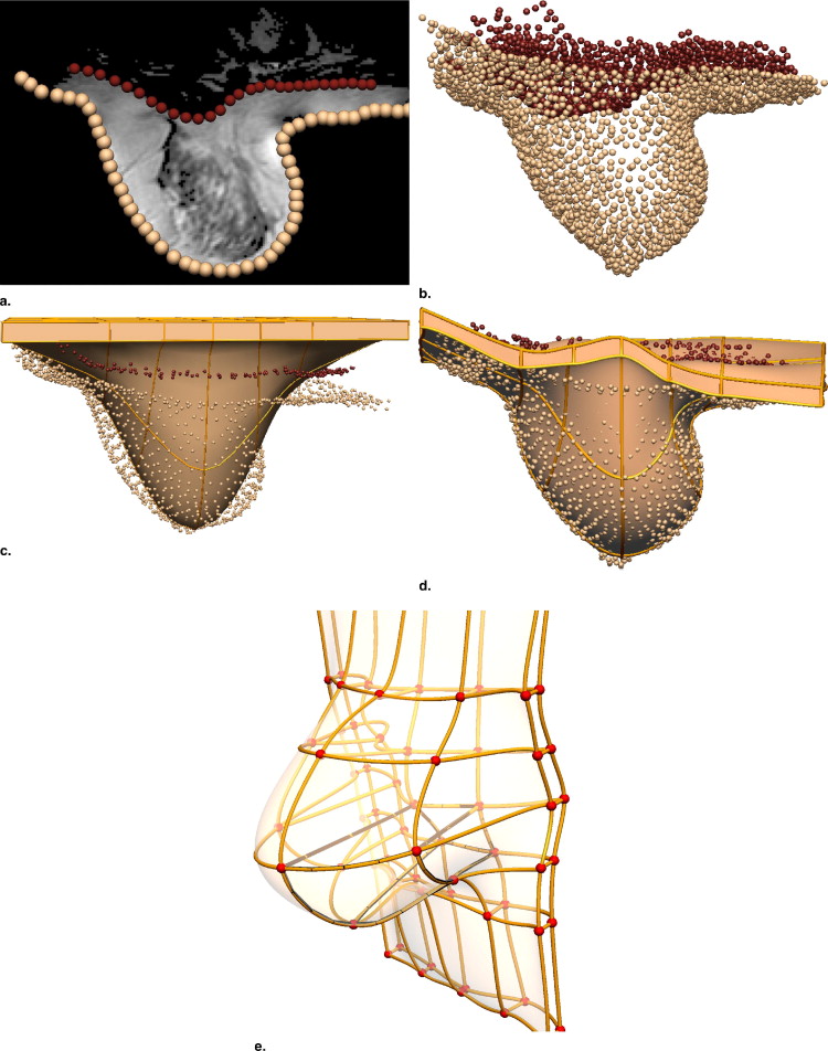
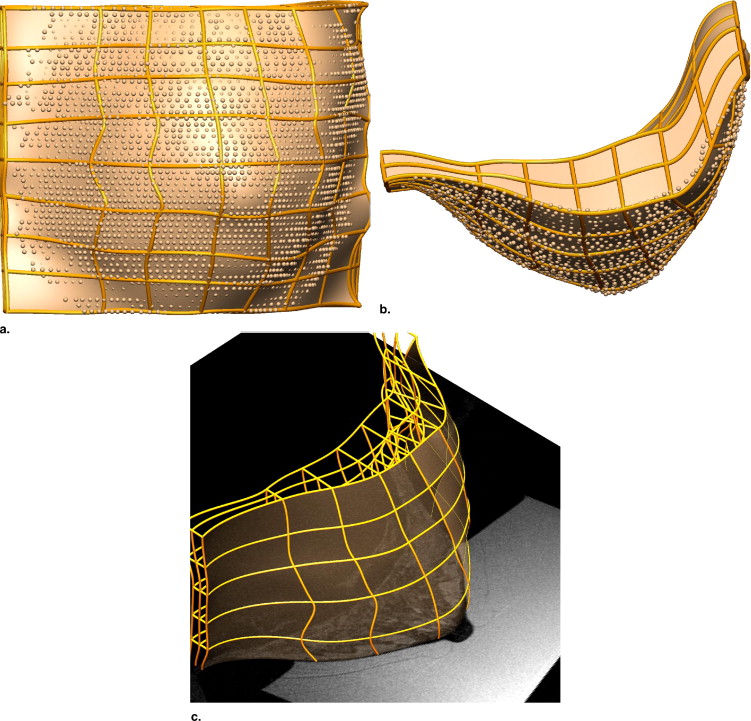
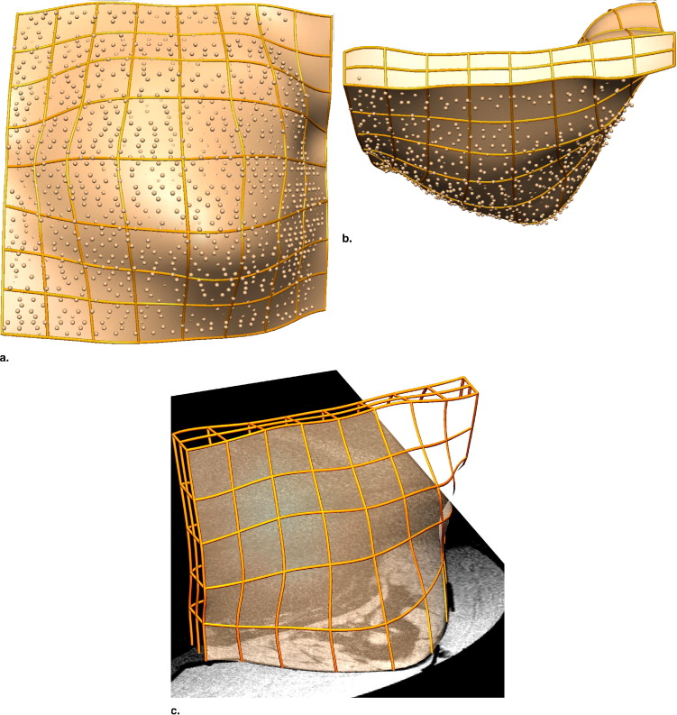
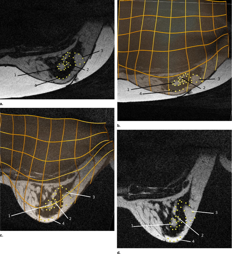
We generate customized finite element models by automatically fitting geometrical models to segmented data from breast MRIs, and characterizing the in vivo mechanical properties (assuming homogeneity) of the breast tissues. For each volunteer, we identified the unloaded configuration by acquiring MRIs of the breast under neutral buoyancy (immersed in water). Such imaging is clearly not practical in the clinical setting; however, these previously unavailable data provide us with important data with which to validate models of breast biomechanics. Internal tissue features were identified in the neutral buoyancy images and tracked to the prone gravity-loaded state using the modeling framework.
Results
The models predicted deformations with root-mean-square errors of 4.2 and 3.6 mm in predicting the skin surface of the gravity-loaded state for each volunteer. Internal tissue features were tracked with a mean error of 3.7 and 4.7 mm for each volunteer.
Conclusions
The models capture breast shape and internal deformations across the images with clinically acceptable accuracy. Further refinement of the framework and incorporation of more anatomic detail will make these models useful for breast cancer diagnosis.
Breast cancer diagnosis involves the careful examination and analysis of clinical images across multiple views and imaging modalities including x-ray mammography, magnetic resonance imaging (MRI), and ultrasound. In analyzing these images, the clinician must interpret the image patterns (noting that each modality measures a different quantity, mammograms measuring x-ray radiation) and track suspicious lesions across these views to determine their state. Apart from the complexity of inferring and mapping across different image patterns, the analysis is further complicated by the fact that the breast is a soft biologic tissue. Its shape changes significantly during any imaging procedure because of mechanical loads such as gravity or compression. Consequently, internal tissue configurations are substantially different across the images that are obtained for diagnosis.
To alleviate these difficulties, significant efforts have been made in the field of image registration ( ). Traditionally, registration algorithms have used image intensity–based statistics, such as mutual information, to determine the optimal transformation for aligning the images ( ). However, the transformations are free form and therefore do not necessarily give physically plausible alignments. To this end, there is increasing interest in the development of biomechanical models of the breast that simulate the deformations and constrain the transformations to be physically admissible ( ).
Get Radiology Tree app to read full this article<
Get Radiology Tree app to read full this article<
Get Radiology Tree app to read full this article<
Get Radiology Tree app to read full this article<
Materials and methods
Volunteers and MRI Acquisition
Get Radiology Tree app to read full this article<
Get Radiology Tree app to read full this article<
Modeling Large Deformations: Finite Elasticity Theory
Get Radiology Tree app to read full this article<
Kinematics
Get Radiology Tree app to read full this article<
Get Radiology Tree app to read full this article<
Get Radiology Tree app to read full this article<
Equilibrium Equations
Get Radiology Tree app to read full this article<
Get Radiology Tree app to read full this article<
Get Radiology Tree app to read full this article<
Imaging the Breast in the Neutral Buoyancy Configuration
Get Radiology Tree app to read full this article<
Get Radiology Tree app to read full this article<
Get Radiology Tree app to read full this article<
Get Radiology Tree app to read full this article<
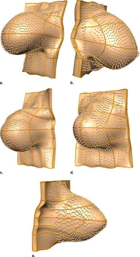
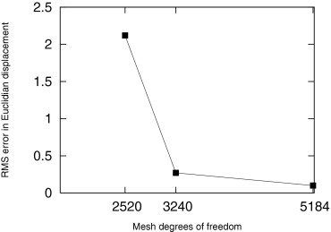
Creating Individual-specific Breast Models
Get Radiology Tree app to read full this article<
Get Radiology Tree app to read full this article<
Get Radiology Tree app to read full this article<
Get Radiology Tree app to read full this article<
Get Radiology Tree app to read full this article<
Loading and Boundary Conditions
Get Radiology Tree app to read full this article<
Characterizing Individual-specific In Vivo Mechanical Properties
Get Radiology Tree app to read full this article<
Get Radiology Tree app to read full this article<
Results
Volunteer 1
Get Radiology Tree app to read full this article<
Get Radiology Tree app to read full this article<
Get Radiology Tree app to read full this article<
Get Radiology Tree app to read full this article<
Get Radiology Tree app to read full this article<
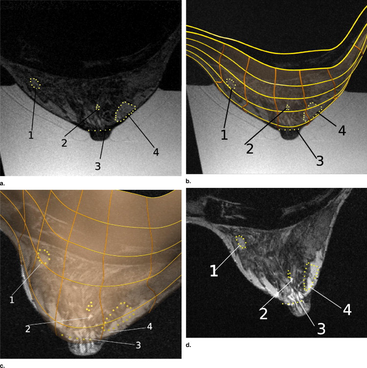
Table 1
Euclidean Distances between Centroids of Actual and Predicted Locations of the Four Tissue Regions Tracked from the Neutral Buoyancy State to the Gravity-loaded Prone Configuration in Volunteer 1
Tissue Region 1 2 3 4 Displacement (mm) 5.1 20.5 19.0 21.7 Euclidean distance (mm) 1.6 4.8 4.5 4.0
Get Radiology Tree app to read full this article<
Volunteer 2
Get Radiology Tree app to read full this article<
Get Radiology Tree app to read full this article<
Get Radiology Tree app to read full this article<
Table 2
Euclidean Distances between Centroids of Actual and Predicted Locations of the Four Tissue Regions Tracked from the Neutral Buoyancy State to the Gravity-loaded Prone Configuration in Volunteer 2
Tissue Region 1 2 3 4 Displacement (mm) 16.9 16.6 17.0 18.0 Euclidean distance (mm) 4.9 5.0 4.0 4.8
Get Radiology Tree app to read full this article<
Discussion
Get Radiology Tree app to read full this article<
Get Radiology Tree app to read full this article<
Get Radiology Tree app to read full this article<
Get Radiology Tree app to read full this article<
Get Radiology Tree app to read full this article<
Get Radiology Tree app to read full this article<
References
1. Wirth M.: A nonrigid approach to medical image registration: matching images of the breast.2000.PhD thesis, RMIT UniversityMelbourne, Australia
2. Dawant B.: Non-rigid registration of medical images: purpose and methods, a short survey. IEEE Int Symp Biomed Imaging 2002; pp. 465-468.
3. Sivaramakrishna R.: 3D breast image registration—a review. Technol Cancer Res Treatment 2005; 4: pp. 39-48.
4. Rueckert D., Sonoda L., Hayes C., et. al.: Nonrigid registration using free-form deformations: application to breast MR images. IEEE Trans Med Imaging 1999; 18: pp. 712-721.
5. Engeland S., Snoeren P., Hendriks J., et. al.: A comparison of methods for mammogram registration. IEEE Trans Med Imaging 2003; 22: pp. 1436-1444.
6. Azar F., Metaxas D., Schnall M.: A finite element model of the breast for predicting mechanical deformations during biopsy procedures. Math Meth Biomed Image Anal 2000; pp. 38-45.
7. Samani A., Bishop J., Yaffe M., et. al.: Biomechanical 3D finite element modeling of the human breast using MRI data. IEEE Trans Med Imaging 2001; 20: pp. 271-279.
8. Tanner C., Schnabel J., Hill D., et. al.: Factors influencing the accuracy of biomechanical breast models. Med Phys J 2006; 33: pp. 1758-1769.
9. Carter T., Tanner C., Crum W., et. al.: Biomechanical model initialized non-rigid registration for image-guided breast surgery.Miller K.Poulikakos D.Computational biomechanics for medicine.2006.MICCAICopenhagen, Denmark:pp. 104-111.
10. Ruiter N., Stotzka R.: Model-based registration of x-ray mammograms and MR images of the female breast. IEEE Trans Nucl Sci 2006; 53: pp. 204-211.
11. Pathmanathan P., Gavaghan D., Whiteley J., et. al.: Predicting tumour location by simulating large deformations of the breast using a 3D finite element model and nonlinear elasticity. Lect Notes Comput Sci 2004; 3217: pp. 217-224.
12. Yu-Neifert Q.: A three-dimensional finite element model to predict the applicability of holographic interferometry to breast tumour detection.1995.PhD thesis, Graduate Faculty of the University of Akron
13. Atkin R., Fox N.: An introduction to the theory of elasticity.1980.Longman GroupLondon
14. Zienkiewicz O., Taylor R.: The finite element method: the basis. vol 15th ed2000.Butterworth-HeinemannOxford, UK
15. Malvern L.: Introduction to the mechanics of a continuous medium.1969.Prentice-HallNew Jersey
16. Rajagopal V., Chung J., Bullivant D., et. al.: Finite elasticity: determining the reference state from a loaded configuration. Int J Numerical Methods Engin 2007; 72: pp. 1434-1451.
17. Valentin J.: Basic anatomical and physiological data for use in radiological protection: reference values. Ann ICRP 2002; 89: pp. 1-277.
18. Rice J.E.: Breast prosthesis (November 1991). http://www.freepatentsonline.com/5066302.html Accessed September 5, 2008
19. Bradley C., Pullan A., Hunter P.: Geometric modelling of the human torso using cubic Hermite elements. Ann Biomed Engin 1997; 25: pp. 96-111.
20. Nielsen P.: The anatomy of the heart: a finite element model.1987.PhD thesis, University of Auckland
21. Fernandez J., Mithraratne P., Thrupp S., et. al.: Anatomically based geometric modelling of the musculo-skeletal system and other organs. Biomech Modeling Mechanobiol 2004; 2: pp. 139-155.
22. Sarvazyan A., Skovoroda A., Emelianov S., et. al.: Biophysical bases of elasticity imaging. Acoust Imaging 1995; 21: pp. 223-240.
23. Chung J., Rajagopal V., Nielsen P., et. al.: A biomechanical model of mammographic compressions. Biomech Modeling Mechanobiol 2008; 7: pp. 43-52.
24. Chung J., Rajagopal V., Laursen T., et. al.: Frictional contact mechanics methods for soft materials: application to tracking breast cancers. J Biomech 2008; 41: pp. 69-77.