
Rationale and Objectives
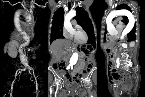
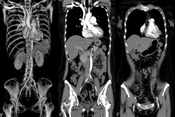
The latest multislice computed tomography (MSCT) scanners permit the chest and abdomen to be scanned continuously. However, conventionally, it has been necessary to perform scanning twice using different pitch factors for the cardiac and abdominal regions. We have developed a new scanning technique known as variable pitch factor scanning, in which the table speed is changed during scanning to obtain continuous images from the heart to the abdomen in a single scan, and have evaluated its physical characteristics.
Materials and Methods
A bead phantom, a comb phantom, and a gold wire placed at an angle were scanned using a 64-row MSCT scanner. The variation in the spatial resolution and continuity of images in the body axis direction because of changes in the pitch factor were evaluated.
Results
Because reconstruction taking the cone angle into consideration was employed, the spatial resolution in the body axis direction was unchanged and the continuity of images in the body axis direction was maintained at a certain level even when the pitch factor was changed.
Conclusion
Variable pitch factor scanning is a useful technique for obtaining continuous images from the heart to the abdomen in a single scan.
Coronary artery stenosis can be assessed with higher accuracy thanks to the introduction of multislice computed tomography (MSCT) scanners with a larger number of detector rows and high-speed gantry rotation ( ). Furthermore, it is now possible to scan a wide range from the shoulders to the pelvis during a single breathhold and to obtain three-dimensional volume data with no dead angles in a short time ( ). However, because of the large differences in the scanning methods employed, it has not been possible to obtain continuous images of the heart and abdomen in a single scan. In cardiac scanning, a slow table speed with a pitch factor of approximately 0.2 must be used to acquire data in the cardiac phases during which cardiac motion is minimal in all coordinates in the body axis direction. In contrast, in abdominal scanning, a fast table speed with a pitch factor of approximately 1.0 is used to scan a wide range in a short breathhold time.
As a result, with conventional scanning methods, it has been necessary to perform scanning twice at different table speeds for the heart and for the abdomen, making it impossible to obtain continuous images from the heart to the abdomen in a single reconstruction. In the emergency care setting, attempts have been made to scan a wide range with a slow table speed for cardiac scan conditions to assess patients presenting with chest pain to evaluate the three major conditions of myocardial infarction, pulmonary embolism, and aortic dissection at one time (triple rule-out) ( ). However, the exposure dose with this method is high and as a result has not gained widespread clinical acceptance.
Get Radiology Tree app to read full this article<
Get Radiology Tree app to read full this article<
Materials and methods
Get Radiology Tree app to read full this article<
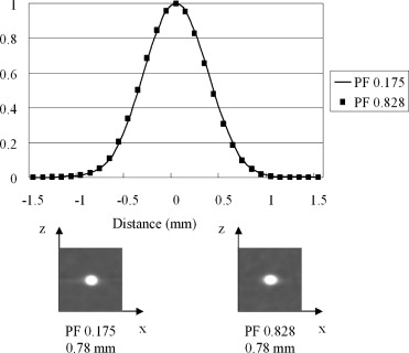
Bead Phantom
Get Radiology Tree app to read full this article<
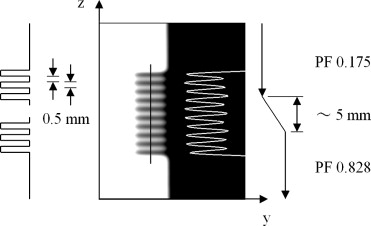
Comb Phantom
Get Radiology Tree app to read full this article<
Get Radiology Tree app to read full this article<
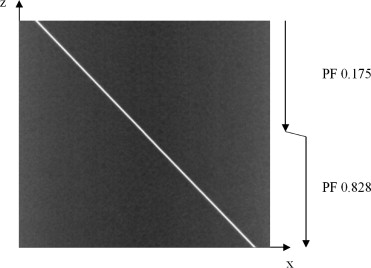
Gold Wire Placed at an Angle
Get Radiology Tree app to read full this article<
Results
Bead Phantom
Get Radiology Tree app to read full this article<
Get Radiology Tree app to read full this article<
Comb Phantom
Get Radiology Tree app to read full this article<
Get Radiology Tree app to read full this article<
Gold Wire Placed at an Angle
Get Radiology Tree app to read full this article<
Get Radiology Tree app to read full this article<
Discussion
Get Radiology Tree app to read full this article<
Get Radiology Tree app to read full this article<
Get Radiology Tree app to read full this article<
Get Radiology Tree app to read full this article<
References
1. Ropers D., Rixe J., Anders K., et. al.: Usefulness of multidetector row spiral computed tomography with 64- × 0.6-mm collimation and 330-ms rotation for the noninvasive detection of significant coronary artery stenoses. Am J Cardiol 2006; 97: pp. 343-348.
2. Raff G.L., Gallagher M.J., O’Neill W.W., et. al.: Diagnostic accuracy of noninvasive coronary angiography using 64-slice spiral computed tomography. J Am Coll Cardiol 2005; 46: pp. 552-557.
3. Flohr T.G., Schaller S., Stierstorfer K., et. al.: Multi-detector row CT systems and image-reconstruction techniques. Radiology 2005; 235: pp. 756-773.
4. Limkakeng A.T., Halpern E., Takakuwa K.M.: Sixty-four-slice multidetector computed tomography: the future of ED cardiac care. Am J Emerg Med 2007; 25: pp. 450-458.
5. Schussler J.M., Smith E.R.: Sixty-four-slice computed tomographic coronary angiography: will the “triple rule out” change chest pain evaluation in the ED?. Am J Emerg Med 2007; 25: pp. 367-375.
6. Taguchi K., Chiang B.S., Hein I.A.: Direct cone-beam cardiac reconstruction algorithm with cardiac banding artifact correction. Med Phys 2006; 33: pp. 521-539.
7. Taguchi K., Chiang B.S., Silver M.D.: A new weighting scheme for cone-beam helical CT to reduce the image noise. Phys Med Biol 2004; 49: pp. 2351-2364.
8. Tsukagoshi S., Ota T., Fujii M., et. al.: Improvement of spatial resolution in the longitudinal direction for isotropic imaging in helical CT. Phys Med Biol 2007; 52: pp. 791-801.
9. Hu H.: Multi-slice helical CT: scan and reconstruction. Med Phys 1999; 26: pp. 5-18.
10. Taguchi K., Aradate H.: Algorithm for image reconstruction in multi-slice helical CT. Med Phys 1998; 25: pp. 550-561.
11. Bricault I., Ferretti G.: A general tool for the evaluation of spiral CT interpolation algorithms: revisiting the effect of pitch in multislice CT. IEEE Trans Med Imaging 2005; 24: pp. 58-69.
12. Hsieh J.: Analytical models for multi-slice helical CT performance parameters. Med Phys 2003; 30: pp. 169-178.