
Rationale and Objectives
To evaluate the potential of high-pitch, dual-source computed tomography (DSCT) for compensation of motion artifacts.
Materials and Methods
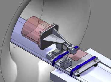
Motion artifacts were created using a moving chest/cardiac phantom with integrated stents at different velocities (from 0 to 4-6 cm/s) parallel (z direction), transverse (x direction), and diagonal (x and z direction combined) to the scanning direction using standard-pitch (SP) (pitch = 1) and high-pitch (HP) (pitch = 3.2) 128-detector DSCT (Siemens, Healthcare, Forchheim, Germany). The scanning parameters were (SP/HP): tube voltage, 120 kV/120 kV; effective tube current time product, 300 mAs/500 mAs; and a pitch of 1/3.2. Motion artifacts were analyzed in terms of subjective image quality and object distortion. Image quality was rated by two blinded, independent observers using a 4-point scoring system (1, excellent; 2, good with minor object distortion or blurring; 3, diagnostically partially not acceptable; and 4, diagnostically not acceptable image quality). Object distortion was assessed by the measured changes of the object’s outer diameter (x) and length (z) and a corresponding calculated distortion vector (d) (d = √(x 2 + z 2 )).
Results
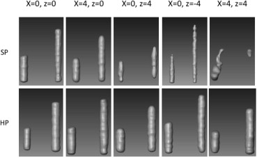
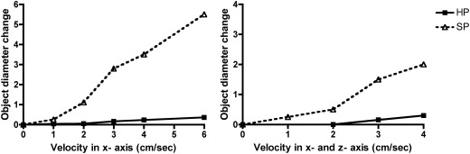
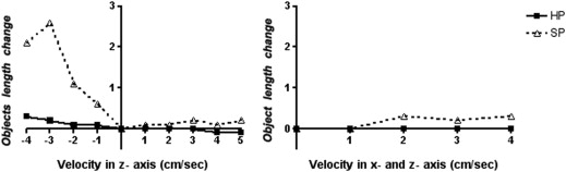
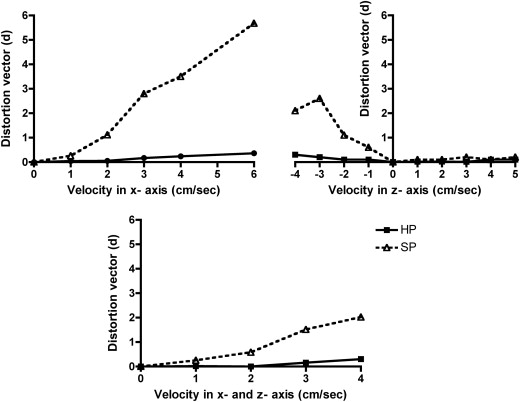
The interobserver agreement was excellent ( k = 0.91). Image quality using SP was diagnostically not acceptable with any motion in x direction (scores 3 and 4), in contrast to HP DSCT where it remained diagnostic up to 2 cm/s (scores 1 and 2). For motion in the z direction only, image quality remained diagnostic for SP and HP DSCT (scores 1 and 2). Changes of the object’s diameter (x), length (z), and distortion vectors (d) were significantly greater with SP (overall: x = 1.9 cm ± 1.7 cm, z = 0.6 cm ± 0.8 cm, and d = 1.4 cm ± 1.5 cm) compared to HP DSCT (overall: x = 0.1 cm ± 0.1 cm, z = 0.0 cm ± 0.1 cm, and d = 0.1 cm ± 0.1 cm; each P < .05).
Conclusion
High-pitch DSCT significantly decreases motion artifacts in various directions and improves image quality.
Computed tomography (CT) is increasingly used for the diagnostic workup of patients. Its speed and accuracy is, particularly in the emergency medicine setting , of utmost importance. Motion artifacts decrease the image quality, resulting in blurring, shading, or streaking of the image and decreasing the accuracy of the diagnosis . Avoidance of motion artifacts would be the most reasonable option. However, patients’ involuntary motions are often unavoidable, particularly in the emergency setting when they are in pain, have orthopnea, decreased consciousness or are small children.
Several technical options have been introduced to reduce the severity of motion artifacts, including 1) prospective and/or retrospective electrocardiogram (ECG) gating to decrease cardiac motion artifacts, 2) over- and underscan modes, and 3) postprocessing methods and software correction algorithms . Decreasing the scan time can further reduce motion artifact. The recently introduced second-generation dual-source CT (DSCT) systems allows to scan at very high-pitch (HP) values, up to 3.2 by using two tube detector systems simultaneously to achieve gapless projection data and increase the temporal resolution (up to 75 ms) . This allows a chest CT to be performed in less than 1 second . This rapid data acquisition may render the HP mode less prone to motion artifacts compared to standard-pitch (SP) acquisitions. In addition, the new 128-slice DSCT permits prospective ECG-synchronized high-pitch acquisitions, resulting in the ability to scan the entire heart within one cardiac cycle . This allows achieving similar image quality with significant decreased radiation doses compared to a retrospective, ECG-gated, low-pitch spiral acquisition mode .
Get Radiology Tree app to read full this article<
Materials and methods
Phantom Information
Get Radiology Tree app to read full this article<
Get Radiology Tree app to read full this article<
CT Scanner Information and Scanning Parameters
Get Radiology Tree app to read full this article<
Get Radiology Tree app to read full this article<
Scanning Modes: Motion Artifacts Created with Different Velocities and Directions
Get Radiology Tree app to read full this article<
Image Quality Evaluation
Get Radiology Tree app to read full this article<
Get Radiology Tree app to read full this article<
Get Radiology Tree app to read full this article<
Object Distortion Evaluation
Get Radiology Tree app to read full this article<
Get Radiology Tree app to read full this article<
Get Radiology Tree app to read full this article<
Get Radiology Tree app to read full this article<
Get Radiology Tree app to read full this article<
Statistical Analysis
Get Radiology Tree app to read full this article<
Results
Subjective Image Quality
Get Radiology Tree app to read full this article<
Get Radiology Tree app to read full this article<
Table 1
Noise as SD of HU Expressed as the Mean of Three Measurements in the Phantom and Subjective Image Quality for Motion in X Direction, Z Direction, and in X and Z Direction Combined Using SP and HP Acquisitions
Subjective Image Quality Noise (HU) (Mean ± SD) SP HP SP HP_P_ Value R1 R2 R1 R2 Overall 21.2 ± 3.8 21.0 ± 1.1 .8 x = 1; z = 0 17.4 21.5 3 3 1 1 x = 2; z = 0 20.3 19.1 4 4 1 1 x = 3; z = 0 23.9 20.0 4 4 3 3 x = 4; z = 0 27.5 20.6 4 4 3 3 x = 6; z = 0 25.4 22.5 4 4 4 4 Total in the x direction 22.9 ± 4.0 20.8 ± 1.3 .29 x = 0; z = 1 18.3 21.1 1 1 1 1 x = 0; z = 2 20.1 19.4 1 1 1 1 x = 0; z = 3 18.0 18.7 2 2 1 1 x = 0; z = 4 20.5 22.0 2 2 1 1 x = 0; z = 5 30.7 22.2 2 2 2 2 x = 0; z = −1 18.6 22.8 1 1 1 1 x = 0; z = −2 16.7 20.3 1 1 1 1 x = 0; z = −3 20.6 21.0 2 2 1 1 x = 0; z = −4 22.6 18.4 2 2 1 1 Total in the z direction 20.7 ± 4.2 21.1 ± 0.6 .78 x = 1; z = 1 17.9 20.6 3 3 1 1 x = 2; z = 2 22.7 20.6 4 4 2 2 x = 3; z = 3 18.3 21.8 4 4 2 3 x = 4; z = 4 22.5 21.4 4 4 3 3 Total in the x and z directions combined 20.4 ± 2.5 21.1 ± 0.6 ∗
HP, high pitch; HU, Hounsfield units; R1, reader 1; R2, reader 2; SD, standard deviation; SP, standard pitch.
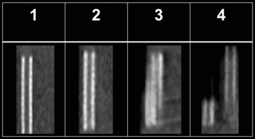
Subjective image quality was evaluated using a 4-point scoring system (1, excellent image quality without visible object distortion or image blurring; 2, good image quality with minor object distortion or blurring; 3, diagnostically partially not acceptable image quality or intermediate blurring; and 4, diagnostically not acceptable image quality with severe object distortion or blurring).
Get Radiology Tree app to read full this article<
Get Radiology Tree app to read full this article<
Object Distortion
Get Radiology Tree app to read full this article<
Table 2
Object Diameter Change, Object Length Change, and the Calculated Distortion Vectors (d = √(x 2 + z 2 )) for SP and HP modes
SP HP_P_ Value Object diameter change Overall (cm) 1.9 ± 1.7 0.1 ± 0.1 <.05 x direction (cm) 2.2 ± 2.1 0.1 ± 0.1 <.05 z direction (cm) 0 0 x and z direction (cm) 0.9 ± 0.9 0.1 ± 0.1 ∗ Object length change Overall (cm) 0.6 ± 0.8 0.0 ± 0.1 <.05 x direction (cm) 0 0 z direction (cm) 0.7 ± 0.9 0.1 ± 0.1 <.05 x and z direction (cm) 0.2 ± 0.2 0 ∗ Distortion vector Overall (cm) 1.4 ± 1.5 0.1 ± 0.1 <.05 x direction (cm) 2.2 ± 2.2 0.1 ± 0.1 <.05 z direction (cm) 0.7 ± 0.9 0.1 ± 0.1 <.05 x and z direction (cm) 0.9 ± 0.9 0.1 ± 0.1 ∗
HP, high-pitch; SP, standard-pitch.
Get Radiology Tree app to read full this article<
Get Radiology Tree app to read full this article<
Get Radiology Tree app to read full this article<
Get Radiology Tree app to read full this article<
Get Radiology Tree app to read full this article<
Get Radiology Tree app to read full this article<
Image Noise
Get Radiology Tree app to read full this article<
Discussion
Get Radiology Tree app to read full this article<
Get Radiology Tree app to read full this article<
Get Radiology Tree app to read full this article<
Get Radiology Tree app to read full this article<
Get Radiology Tree app to read full this article<
Get Radiology Tree app to read full this article<
Get Radiology Tree app to read full this article<
Get Radiology Tree app to read full this article<
Uncited figure
Get Radiology Tree app to read full this article<
References
1. Broder J., Warshauer D.M.: Increasing utilization of computed tomography in the adult emergency department, 2000-2005. Emerg Radiol 2006; 13: pp. 25-30.
2. Broder J., Fordham L.A., Warshauer D.M.: Increasing utilization of computed tomography in the pediatric emergency department, 2000-2006. Emerg Radiol 2007; 14: pp. 227-232.
3. Rao V.M., Levin D.C., Parker L., et. al.: Trends in utilization rates of the various imaging modalities in emergency departments: nationwide Medicare data from 2000 to 2008. J Am Coll Radiol 2011; 8: pp. 706-709.
4. Barrett J.F., Keat N.: Artifacts in CT: recognition and avoidance. Radiographics 2004; 24: pp. 1679-1691.
5. Ha H.I., Goo H.W., Seo J.B., et. al.: Effects of high-resolution CT of the lung using partial versus full reconstruction on motion artifacts and image noise. AJR Am J Roentgenol 2006; 187: pp. 618-622.
6. Shuman W.P., Leipsic J.A., Busey J.M., et. al.: Prospectively ECG gated CT pulmonary angiography versus helical ungated CT pulmonary angiography: impact on cardiac related motion artifacts and patient radiation dose. Eur J Radiol 2012; 81: pp. 2444-2449.
7. Blanke P., Bulla S., Baumann T., et. al.: Thoracic aorta: prospective electrocardiographically triggered CT angiography with dual-source CT—feasibility, image quality, and dose reduction. Radiology 2010; 255: pp. 207-217.
8. Law W.-Y., Yang C.-C., Chen L.-K., et. al.: Retrospective gating vs. prospective triggering for noninvasive coronary angiography: assessment of image quality and radiation dose using a 256-slice CT scanner with 270 ms gantry rotation. Acad Radiol 2011; 18: pp. 31-39.
9. Lell M., Hinkmann F., Anders K., et. al.: High-pitch electrocardiogram-triggered computed tomography of the chest: initial results. Invest Radiol 2009; 44: pp. 728-733.
10. Flohr T.G., Leng S., Yu L., et. al.: Dual-source spiral CT with pitch up to 3.2 and 75 ms temporal resolution: image reconstruction and assessment of image quality. Med Phys 2009; 36: pp. 5641-5653.
11. Flohr T.G., McCollough C.H., Bruder H., et. al.: First performance evaluation of a dual-source CT (DSCT) system. Eur Radiol 2006; 16: pp. 256-268.
12. Sommer W.H., Schenzle J.C., Becker C.R., et. al.: Saving dose in triple-rule-out computed tomography examination using a high-pitch dual spiral technique. Invest Radiol 2010; 45: pp. 64-71.
13. Achenbach S., Marwan M., Schepis T., et. al.: High-pitch spiral acquisition: a new scan mode for coronary CT angiography. J Cardiovasc Comput Tomogr 2009; 3: pp. 117-121.
14. Leschka S., Stolzmann P., Desbiolles L., et. al.: Diagnostic accuracy of high-pitch dual-source CT for the assessment of coronary stenoses: first experience. Eur Radiol 2009; 19: pp. 2896-2903.
15. Sun K., Han R.-J., Ma L.-J., et. al.: Prospectively electrocardiogram-gated high-pitch spiral acquisition mode dual-source CT coronary angiography in patients with high heart rates: comparison with retrospective electrocardiogram-gated spiral acquisition mode. Korean J Radiol 2012; 13: pp. 684-693.
16. Kröpil P., Rojas C.A., Ghoshhajra B., et. al.: Prospectively ECG-triggered high-pitch spiral acquisition for cardiac CT angiography in routine clinical practice: initial results. J Thorac Imaging 2012; 27: pp. 194-201.
17. Schulz B., Jacobi V., Beeres M., et. al.: Quantitative analysis of motion artifacts in high-pitch dual-source computed tomography of the thorax. J Thorac Imaging 2012; 27: pp. 382-386.
18. Baumueller S., Alkadhi H., Stolzmann P., et. al.: Computed tomography of the lung in the high-pitch mode: is breath holding still required?. Invest Radiol 2011; 46: pp. 240-245.
19. Wolf F., Leschka S., Loewe C., et. al.: Coronary artery stent imaging with 128-slice dual-source CT using high-pitch spiral acquisition in a cardiac phantom: comparison with the sequential and low-pitch spiral mode. Eur Radiol 2010; 20: pp. 2084-2091.
20. Wolf F., Feuchtner G.M., Homolka P., et. al.: In vitro imaging of coronary artery stents: are there differences between 16- and 64-slice CT scanners?. Eur J Radiol 2008; 68: pp. 465-470.
21. Homolka P., Gahleitner A., Prokop M., et. al.: Optimization of the composition of phantom materials for computed tomography. Phys Med Biol 2002; 47: pp. 2907-2916.
22. Goldman L.W.: Principles of CT: radiation dose and image quality. J Nucl Med Technol 2007; 35: pp. 213-225.
23. Graf H., Heuschmid M., Küttner A., et. al.: [Characterization of motion artifacts in multi-slice spiral CT]. Rofo 2002; 174: pp. 1301-1308.
24. Chen G.T., Kung J.H., Beaudette K.P.: Artifacts in computed tomography scanning of moving objects. Semin Radiat Oncol 2004; 14: pp. 19-26.
25. Lewis J.H., Jiang S.B.: A theoretical model for respiratory motion artifacts in free-breathing CT scans. Phys Med Biol 2009; 54: pp. 745-755.
26. Baek J.H., Lee W., Chang K.-H., et. al.: Optimization of the scan protocol for the reduction of diaphragmatic motion artifacts depicted on CT angiography: a phantom study simulating pediatric patients with free breathing. Korean J Radiol 2009; 10: pp. 260-268.
27. Lell M.M., May M., Deak P., et. al.: High-pitch spiral computed tomography: effect on image quality and radiation dose in pediatric chest computed tomography. Invest Radiol 2011; 46: pp. 116-123.
28. Amacker N.A., Mader C., Alkadhi H., et. al.: Routine chest and abdominal high-pitch CT: an alternative low dose protocol with preserved image quality. Eur J Radiol 2012; 81: pp. e392-e397.
29. Groen J.M., Greuter M.J., van Ooijen P.M., et. al.: A new approach to the assessment of lumen visibility of coronary artery stent at various heart rates using 64-slice MDCT. Eur Radiol 2007; 17: pp. 1879-1884.