
Rationale and Objectives
We undertook this study to determine whether differences in detector-lesion distance resulted in appreciable effects on digital magnification mammography performance as measured using the American College of Radiology (ACR) mammography phantom and a line pair test pattern.
Materials and Methods
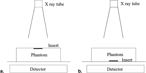
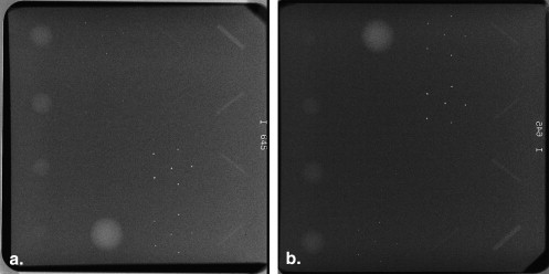
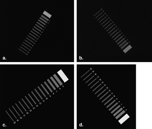
Images of the standard 42-mm thick standard ACR mammography phantom with a wax insert on one side containing simulated fibers, calcifications, and masses were obtained on a Senographe Essential digital mammography system with the phantom in upright and inverted positions. The process was repeated with a line pair test pattern for measuring resolution. All images were obtained in contact mode, and with 1.5× and 1.8× magnification, and evaluated on a GE PACS monitor.
Results
Overall, changing lesion-detector distance using standard versus inverted positioning did not appreciably increase the number of objects seen on the ACR phantom under all modes. No greater than one line pair difference was seen in standard versus inverted positioning. At 1.8× magnification mode, no difference was detected in line pair resolution with a change in positioning.
Conclusion
Differences in lesion-detector distance as modeled using both the ACR mammography phantom and a line pair test pattern did not make an appreciable difference in digital magnification mammography performance.
Magnification mammography works through the principle of geometric magnification, wherein the breast is placed on a support platform at a fixed position above the detector, so that there is an air gap between the breast and the detector. The rate of magnification is the ratio of the source-to-image (x-ray tube to detector) distance to source-to-object (x-ray tube to breast lesion) distance. Increased magnification allows for increased effective resolution, thereby improving lesion detection and characterization .
The most significant limitation of magnification is geometric blurring caused by finite focal spot size. Larger focal spots and higher magnification increases blurring, which causes a loss of resolution in the projected image. To maintain resolution, a smaller focal spot is used, typically 0.1 mm as opposed to the 0.3 mm focal spot for standard contact mammography. The use of smaller focal spots has been shown to improve image quality in magnification mammography .
Get Radiology Tree app to read full this article<
Get Radiology Tree app to read full this article<
Materials and methods
Get Radiology Tree app to read full this article<
Get Radiology Tree app to read full this article<
Get Radiology Tree app to read full this article<
Get Radiology Tree app to read full this article<
Results
Get Radiology Tree app to read full this article<
Table 1
Radiologist Detection of the Objects (Masses, Fibers, Calcifications) within the American College of Radiology Mammography Phantom and Maximum Line Pair Resolution
Radiologist 1 2 3 4 5 Total # of observed masses Contact standard/inverted 4/4 4/4 4/4 4/4 4/4 1.5× standard/inverted 5/5 5/5 5/5 4/4 5/5 1.8× standard/inverted 5/5 5/5 5/5 4/4 5/5 Total # of observed fibers Contact standard/inverted 5/5 5/5 5/5 5/5 5/5 1.5× standard/inverted 5/5 6/5 5/5 5/5 5/5 1.8× standard/inverted 5/5 6/6 6/5 5/5 5/5 Total # of observed calcifications Contact standard/inverted 4/4 4/4 4/4 4/4 4/4 1.5× standard/inverted 4/4 4/4 4/4 4/4 4/4 1.8× standard/inverted 4/4 4/4 4/4 4/4 4/4 Spatial resolution (lp/mm) Contact standard/inverted 8/8 7/6 8/7 8/8 8/8 1.5× standard/inverted 11/10 9/8 11/10 11/10 10/10 1.8× standard/inverted 13/13 10/10 12/12 12/12 12/12
Get Radiology Tree app to read full this article<
Get Radiology Tree app to read full this article<
Get Radiology Tree app to read full this article<
Get Radiology Tree app to read full this article<
Get Radiology Tree app to read full this article<
Discussion
Get Radiology Tree app to read full this article<
Get Radiology Tree app to read full this article<
Table 2
Calculation of Penumbra
Magnification Focal Spot Size Penumbra ∗ Object Closer to Detector (Inverted) Object Farther from Detector (Standard) Contact mode 0.3 mm 11 microns 33 microns 1.5× 0.1 mm 58 microns 76 microns 1.8× 0.1 mm 92 microns 149 microns
Get Radiology Tree app to read full this article<
Get Radiology Tree app to read full this article<
Get Radiology Tree app to read full this article<
Get Radiology Tree app to read full this article<
Get Radiology Tree app to read full this article<
References
1. Bushberg J.T., Seibert J.A., Leidholdt E., et. al.: The essential physics of medical imaging.2nd ed.2002.Lippincott Williams & WilkinsPhiladelphia, PA
2. Koutalonis M., Delis H., Spyrou G., et. al.: Monte Carlo studies on the influence of focal spot size and intensity distribution on spatial resolution in magnification mammography. Phys Med Biol 2008; 53: pp. 1369-1384.
3. Boyce S.J., Samei E.: Imaging properties of digital magnification radiography. Med Phys 2006; 33: pp. 984-996.
4. Eklund G.W., Cardenosa G.: The art of mammographic positioning. Radiol Clin North Am 1992; 30: pp. 21-53.