
Rationale and Objectives
Geometrical distortion is a well-known problem in structural magnetic resonance imaging (MRI), leading to pixel shifts with variations up to several millimeters. Because the main factors of geometrical distortion are proportional to B 0 , MRI spatial encoding distortions tend to increase with higher magnetic field strength. With the increasing prospects of utilizing ultra-high-field MRI (B 0 ≥ 7 Tesla) for neuroimaging and subsequently for image-guided neurosurgical therapy, the evaluation and correction of geometrical distortions occurring in ultra-high-field MRI are essential preconditions for the integration of these data. Hence, we conducted a phantom study to determine hardware-related geometrical distortion in clinically relevant sequences for structural imaging at 7 T MRI and compared the findings to 1.5 T MRI.
Material and Methods
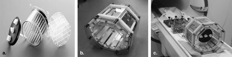
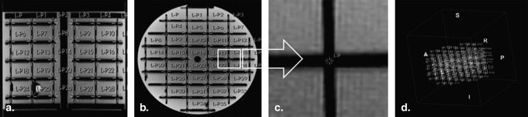
Hardware-related geometrical distortion was evaluated using a MRI phantom (Elekta, Sweden). Both applied scanner systems (Magnetom Avanto 1.5 T and Magnetom 7 T, Siemens Healthcare, Erlangen, Germany) were equipped with similar gradient coils capable of delivering 45 mT/m of maximum amplitude and a slew rate of 220 mT/m/ms. Distortion analysis was performed for various clinically relevant gradient echo and spin echo sequences.
Results
Overall, we found very low mean geometrical distortions at both 7 T and 1.5 T, although single values of up to 1.6 mm were detected. No major differences in mean distortion between the sequences could be found, except significantly higher distortions in turbo spin-echo sequences at 7 T, mainly caused by B 1 inhomogeneities.
Conclusion
Hardware-related geometrical distortions at 7 T MRI are relatively small, which may be acceptable for image coregistration or for direct tissue-targeting procedures. Using a subject-specific correction of object-related distortions, an integration of 7 T MRI data into image-guided applications may be feasible.
The incorporation of magnetic resonance imaging (MRI) data into various neurosurgical procedures has become common clinical routine and is continuously expanding. This accounts in particular for their application in functional and stereotactic neurosurgery. Especially in regard to deep brain stimulation, the growing importance of MRI (eg, for structural targeting) has recently been emphasized . Another important field is image-guided radiosurgery .
Although the application of 3 Tesla (T) field-strength MRI in clinical routine is steadily increasing, higher field-strength systems, specifically 7 T scanners, are still primarily used for scientific or preclinical applications. First experiences from technical studies and single series of volunteers and patients show promising results for both structural and functional imaging . In particular, the delineation of deep brain structures using susceptibility-weighted imaging (SWI) or T2∗-weighted imaging (eg, for deep brain stimulation procedures) has already been shown to be improved at 7 T field strength. The high-resolution structural depiction possible at higher field strengths within reasonable scan time may be valuable for neuronavigated surgery as well. Several exemplary images can be found in Figures 1 and 2 .
 Open full size image
Figure 1
(a–d) Exemplary axial slices of a high-resolution susceptibility-weighted imaging (SWI) sequence at 7 T covering the deep-brain nuclei, starting from a caudal slice. Image contrast at 7 T is mainly generated by the differing tissue T2∗ times, resulting in magnitude and phase differences. 1: subthalamic nucleus; 2: red nucleus, 3: superior colliculus; 4: medial geniculate nucleus; 5: globus pallidus, internal segment; 6: globus pallidus, medial medullary lamina; 7: globus pallidus, external segment; 8: striatum; 9: basal vein; 10: substantia nigra; 11: lateral geniculate nucleus; 12: third ventricle; 13: internal capsule; 14: ventral anterior nucleus; 15: ventral lateral nucleus; 16: dorsomedial nucleus; 17: ventral posterior nucleus; 18: pulvinar nucleus; 19: choroid plexus; 20: globus pallidus; 21: internal cerebral veins.
 Open full size image
Figure 2
Exemplary sagittal images of a clivus chordoma from a contrast-enhanced T1-weighted spin echo (SE) sequence using routine clinical parameters at 1.5 T (a,c) and corresponding slices from a contrast-enhanced T1-weighted fast low-angle shot (FLASH) sequence at 7 T (for sequence parameters, see Table 1 ). Note the clearer depiction of the lesion because of the higher spatial resolution and the sharp contrast differences within the clivus, suggestive of tumor infiltration ( white arrow ).
Get Radiology Tree app to read full this article<
Get Radiology Tree app to read full this article<
Get Radiology Tree app to read full this article<
Materials and methods
Phantom Descriptions
Get Radiology Tree app to read full this article<
Get Radiology Tree app to read full this article<
CT and MRI Measurements
Get Radiology Tree app to read full this article<
Table 1
Scan Parameter Details of the Various Sequences Performed at 1.5 and 7 T
1.5 Tesla MPRAGE FLASH T2 TSE SWI 7 Tesla MPRAGE FLASH T2 TSE SWI Repetition time (ms) 2180 4.77 4570 49 3500 5 4520 29 Echo time (ms) 3.09 1.92 146 40 2.49 2.04 112 15.2 Inversion time (ms) 1100 1100 Nominal flip angle (°) 10 12 150 15 10 12 125 25 Field of view (mm 2 ;) 256 256 220 256 256 256 220 256 Acquisition matrix (pixel) 256 × 256 256 × 256 256 × 512 256 × 256 256 × 256 384 × 384 256 × 512 896 × 672 Bandwidth (Hz/pixel) 130 190 70 75 600 725 350 280 Echo train length (n) 1 1 13 1 1 1 13 1 Slices (n) 240 224 80 60 256 256 86 88 Slice thickness (mm) 1 1 1.5 2 1 0.7 1.5 2 Phase-encoding direction AP L-R AP AP AP L-R AP AP Frequency-encoding direction L-R AP L-R L-R L-R AP L-R L-R Slice-selection direction H-F H-F H-F H-F H-F H-F H-F H-F
AP, anteroposterior; FLASH, fast low-angle shot; H-F, head-feet direction; MPRAGE, magnetization prepared rapid gradient echo; R-L, right-left direction; SWI, susceptibility-weighted imaging; T2 TSE, T2-weighted turbo spin echo.
Get Radiology Tree app to read full this article<
Image Postprocessing
Get Radiology Tree app to read full this article<
e2(R,t,c)−1n∑ni=1||yi−(cRxi+t)||2. e
2
(
R
,
t
,
c
)
−
1
n
∑
i
=
1
n
|
|
y
i
−
(
c
R
x
i
+
t
)
|
|
2
.
Get Radiology Tree app to read full this article<
Get Radiology Tree app to read full this article<
Δx,y,z=(Δx)2+(Δy)2+(Δz)2−−−−−−−−−−−−−−−−−−√. Δ
x
,
y
,
z
=
(
Δ
x
)
2
+
(
Δ
y
)
2
+
(
Δ
z
)
2
.
Get Radiology Tree app to read full this article<
Distortion Correction
Get Radiology Tree app to read full this article<
Results
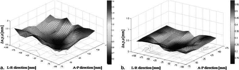
Analysis of Distortions
Get Radiology Tree app to read full this article<
Table 2
Summary of Positional Deviations at 1.5 T (A) and 7 T (B) in all Three Directions (∆ x ∆ y ∆ z )
A ∆x (mm) ∆y (mm) ∆z (mm) ∆ xyz (mm) Acquisition DC Range Mean SD Range Mean SD Range Mean SD Mean SD 1.5 T MPRAGE NA 0–1.3 0.4 ±0.3 0–0.8 0.3 ±0.2 0–0.7 0.2 ±0.2 0.6 ±0.1 MPRAGE 2D 0–1.0 0.4 ±0.3 0–0.8 0.3 ±0.1 0–0.6 0.2 ±0.1 0.6 ±0.1 MPRAGE 3D 0–1.1 0.4 ±0.2 0–0.9 0.3 ±0.2 0–0.6 0.3 ±0.2 0.6 ±0.1 FLASH NA 0–0.9 0.3 ±0.2 0–1.2 0.4 ±0.2 0–0.8 0.3 ±0.3 0.6 ±0.1 FLASH 2D 0–0.6 0.3 ±0.2 0–0.9 0.4 ±0.2 0–0.6 0.2 ±0.2 0.5 ±0.1 FLASH 3D 0–0.7 0.3 ±0.2 0–0.9 0.3 ±0.3 0–0.6 0.2 ±0.1 0.5 ±0.2 T2 NA 0–0.9 0.4 ±0.3 0–0.8 0.3 ±0.2 0–0.6 0.2 ±0.1 0.6 ±0.1 T2 2D 0–0.8 0.4 ±0.2 0–0.8 0.3 ±0.2 0–0.5 0.2 ±0.2 0.6 ±0.1 SWI NA 0–0.7 0.3 ±0.2 0–0.6 0.3 ±0.2 0–0.7 0.3 ±0.2 0.5 ±0.2 SWI 2D 0–0.6 0.3 ±0.1 0–0.5 0.3 ±0.3 0–0.7 0.3 ±0.2 0.5 ±0.1 SWI 3D 0–0.7 0.3 ±0.2 0–0.5 0.3 ±0.2 0–0.5 0.2 ±0.1 0.5 ±0.1
B ∆x (mm) ∆y (mm) ∆z (mm) ∆ xyz (mm) Acquisition DC Range Mean SD Range Mean SD Range Mean SD Mean SD 7 T MPRAGE NA 0–1.3 0.4 ±0.1 0–0.9 0.4 ±0.2 0–1.1 0.2 ±0.1 0.6 ±0.1 MPRAGE 2D 0–1.1 0.4 ±0.2 0–0.8 0.3 ±0.1 0–0.7 0.2 ±0.2 0.6 ±0.1 MPRAGE 3D 0–1.2 0.4 ±0.2 0–0.8 0.3 ±0.1 0–0.7 0.2 ±0.1 0.5 ±0.1 FLASH NA 0–0.5 0.2 ±0.1 0–0.8 0.3 ±0.2 0–0.4 0.1 ±0.1 0.5 ±0.1 FLASH 2D 0–0.5 0.3 ±0.1 0–0.8 0.3 ±0.2 0–0.6 0.2 ±0.2 0.5 ±0.1 FLASH 3D 0–0.5 0.2 ±0.1 0–0.7 0.3 ±0.2 0–0.6 0.2 ±0.1 0.5 ±0.1 T2 NA 0–1.2 0.5 ±0.3 0–1.6 0.6 ±0.4 0.2–1.4 0.6 ±0.3 1.0 ±0.2 T2 2D 0–1.3 0.5 ±0.2 0–1.5 0.6 ±0.3 0–1.4 0.7 ±0.2 1.1 ±0.2 SWI NA 0–0.5 0.2 ±0.1 0–0.6 0.3 ±0.2 0–0.8 0.3 ±0.2 0.5 ±0.1 SWI 2D 0–0.6 0.2 ±0.2 0–0.8 0.2 ±0.2 0–0.6 0.3 ±0.1 0.5 ±0.1 SWI 3D 0–0.4 0.2 ±0.1 0–1.0 0.3 ±0.1 0–0.7 0.3 ±0.2 0.5 ±0.1
∆ x , right-left; ∆ y , anteroposterior; ∆ z , head-feet; 2D, two-dimensional; 3D, three-dimensional; DC, distortion correction; FLASH, fast low-angle shot; MPRAGE, magnetization prepared rapid gradient echo; NA, with manufacturer-provided DC; SD, standard deviation; SWI, susceptibility-weighted imaging.
Sequences were acquired without (NA) or with the manufacturer-provided DC in 2D or 3D, where applicable. Values are given as range and mean ± SD. Overall deviation is given as ∆ x,y,z . All values are given in millimeters, rounded to the first decimal place.
Get Radiology Tree app to read full this article<
Get Radiology Tree app to read full this article<
Get Radiology Tree app to read full this article<
Get Radiology Tree app to read full this article<
Discussion
Get Radiology Tree app to read full this article<
Get Radiology Tree app to read full this article<
Get Radiology Tree app to read full this article<
Get Radiology Tree app to read full this article<
Get Radiology Tree app to read full this article<
Conclusion
Get Radiology Tree app to read full this article<
References
1. Lozano A.M.: Deep brain stimulation for Parkinson disease. J Neurosurg 2010; 112: pp. 477. discussion 478
2. Zrinzo L.: The role of imaging in the surgical treatment of movement disorders. Neuroimag Clin N Am 2010; 20: pp. 125-140.
3. Alexander E., Kooy H.M., van Herk M., et. al.: Magnetic resonance image-directed stereotactic neurosurgery: use of image fusion with computerized tomography to enhance spatial accuracy. J Neurosurg 1995; 83: pp. 271-276.
4. Burchiel K.J., Nguyen T.T., Coombs B.D., et. al.: MRI distortion and stereotactic neurosurgery using the Cosman-Roberts-Wells and Leksell frames. Stereotact Funct Neurosurg 1996; 66: pp. 123-136.
5. Derosier C., Delegue G., Munier T., et. al.: [MRI, geometric distortion of the image and stereotaxy]. J Radiol 1991; 72: pp. 349-353.
6. Fransson A., Andreo P., Potter R.: Aspects of MR image distortions in radiotherapy treatment planning. Strahlenther Onkol 2001; 177: pp. 59-73.
7. Novotny J., Vymazal J., Novotny J., et. al.: Does new magnetic resonance imaging technology provide better geometrical accuracy during stereotactic imaging?. J Neurosurg 2005; 102: pp. 8-13.
8. Yu C., Petrovich Z., Apuzzo M.L., et. al.: An image fusion study of the geometric accuracy of magnetic resonance imaging with the Leksell stereotactic localization system. J Appl Clin Med Phys 2001; 2: pp. 42-50.
9. Dammann P., Barth M., Zhu Y., et. al.: Susceptibility-weighted imaging of cerebral cavernous malformations - prospects, drawbacks and first experience at ultra-high-field (7 Tesla) MRI. Neurosurg Focus 2010; 29: pp. E5.
10. Yuh W.T., Christoforidis G.A., Koch R.M., et. al.: Clinical magnetic resonance imaging of brain tumors at ultrahigh field: a state-of-the-art review. Top Magn Reson Imaging 2006; 17: pp. 53-61.
11. Moenninghoff C, Maderwald S, Theysohn JM, et al. Imaging of adult astrocytic brain tumours with 7 T MRI: preliminary results. Eur Radiol 20:704–713.
12. Moenninghoff C., Kraff O., Schlamann M., et. al.: Assessing a dysplastic cerebellar gangliocytoma (Lhermitte-Duclos disease) with 7T MR imaging. Korean J Radiol 2010; 11: pp. 244-248.
13. Kollia K., Maderwald S., Putzki N., et. al.: First clinical study on ultra-high-field MR imaging in patients with multiple sclerosis: comparison of 1.5T and 7T. AJNR 2009; 30: pp. 699-702.
14. Ladd M.E.: High-field-strength magnetic resonance: potential and limits. Top Magn Reson Imaging 2007; 18: pp. 139-152.
15. O’Donnell M., Edelstein W.A.: NMR imaging in the presence of magnetic field inhomogeneities and gradient field nonlinearities. Med Phys 1985; 12: pp. 20-26.
16. Spiegelmann R., Nissim O., Daniels D., et. al.: Stereotactic targeting of the ventrointermediate nucleus of the thalamus by direct visualization with high-field MRI. Stereotact Funct Neurosurg 2006; 84: pp. 19-23.
17. Walton L., Hampshire A., Forster D.M., et. al.: A phantom study to assess the accuracy of stereotactic localization, using T1-weighted magnetic resonance imaging with the Leksell stereotactic system. Neurosurgery 1996; 38: pp. 1705-1706. discussion 6–8
18. Archip N., Clatz O., Whalen S., et. al.: Compensation of geometric distortion effects on intraoperative magnetic resonance imaging for enhanced visualization in image-guided neurosurgery. Neurosurgery 2008; 62: pp. 209-215. discussion 15–16
19. Burkhardt S., Schweikard A., Burgkart R.: Numerical determination of the susceptibility caused geometric distortions in magnetic resonance imaging. Med Image Anal 2003; 7: pp. 221-236.
20. Chang H., Fitzpatrick J.M.: A technique for accurate magnetic resonance imaging in the presence of field inhomogeneities. IEEE Trans Med Imaging 1992; 11: pp. 319-329.
21. Karger C.P., Hoss A., Bendl R., et. al.: Accuracy of device-specific 2D and 3D image distortion correction algorithms for magnetic resonance imaging of the head provided by a manufacturer. Phys Med Biol 2006; 51: pp. N253-N261.
22. Maciunas R.J., Galloway R.L., Latimer J.W.: The application accuracy of stereotactic frames. Neurosurgery 1994; 35: pp. 682-694. discussion 94–95
23. Menuel C., Garnero L., Bardinet E., et. al.: Characterization and correction of distortions in stereotactic magnetic resonance imaging for bilateral subthalamic stimulation in Parkinson disease. J Neurosurg 2005; 103: pp. 256-266.
24. Sumanaweera T., Glover G., Song S., et. al.: Quantifying MRI geometric distortion in tissue. Magn Reson Med 1994; 31: pp. 40-47.
25. Watanabe Y., Lee C.K., Gerbi B.J.: Geometrical accuracy of a 3-tesla magnetic resonance imaging unit in Gamma Knife surgery. J Neurosurg 2006; 105: pp. 190-193.
26. Bakker C.J., Moerland M.A., Bhagwandien R., et. al.: Analysis of machine-dependent and object-induced geometric distortion in 2DFT MR imaging. Magnet Res Imaging 1992; 10: pp. 597-608.
27. Haacke E., Brown R., Thompson M.: Magnetic resonance imaging: physical principles and sequence design.1999.John Wiley and SonsNew York
28. Oppelt A.: Imaging systems for medical diagnostics. Fundamentals, technical solutions and applications for systems applying ionizing radiation, nuclear magnetic resonance and ultrasound.2005.Publicis Corporate PublishingErlangen, Germany
29. Wang D., Doddrell D.M.: Geometric distortion in structural magnetic resonance imaging. Curr Med Imaging Rev 2005; 1: pp. 49-60.
30. Ludeke K.M., Roschmann P., Tischler R.: Susceptibility artefacts in NMR imaging. Magnet Reson Imaging 1985; 3: pp. 329-343.
31. Schenck J.F.: The role of magnetic susceptibility in magnetic resonance imaging: MRI magnetic compatibility of the first and second kinds. Med Phys 1996; 23: pp. 815-850.
32. Wang D., Strugnell W., Cowin G., et. al.: Geometric distortion in clinical MRI systems Part I: evaluation using a 3D phantom. Magnet Reson Imaging 2004; 22: pp. 1211-1221.
33. Kangarlu A., Baertlein B.A., Lee R., et. al.: Dielectric resonance phenomena in ultra high field MRI. J Computer Assisted Tomogr 1999; 23: pp. 821-831.
34. Gerdes J.S., Hitchon P.W., Neerangun W., et. al.: Computed tomography versus magnetic resonance imaging in stereotactic localization. Stereotact Funct Neurosurg 1994; 63: pp. 124-129.
35. Fitzpatrick J.M., Hill D.L., Shyr Y., et. al.: Visual assessment of the accuracy of retrospective registration of MR and CT images of the brain. IEEE Trans Med Imaging 1998; 17: 571–185
36. Maurer C.R., Fitzpatrick J.M., Wang M.Y., et. al.: Registration of head volume images using implantable fiducial markers. IEEE Trans Med Imaging 1997; 16: pp. 447-462.
37. Cho Z.H., Min H.K., Oh SH, et. al.: Direct visualization of deep brain stimulation targets in Parkinson disease with the use of 7-tesla magnetic resonance imaging. J Neurosurg 2010; 113: pp. 639-647.
38. Orzada S., Kraff O., Brote I., et. al.: 8-channel transmit/receive head coil for 7 T human imaging using intrinsically decoupled strip line elements with meanders.2009.Proc 17th Annu Meeting ISMRMHonolulu, HI
39. Umeyama S.: Least-squares estimation of transformation parameters between two point patterns. IEEE Tran Pattern Anal Machine Intell 1991; 13: pp. 376-380.
40. Wang D., Strugnell W., Cowin G., et. al.: Geometric distortion in clinical MRI systems Part II: correction using a 3D phantom. Magnet Reson Imaging 2004; 22: pp. 1223-1232.
41. Setsompop K., Alagappan V., Zelinski A.C., et. al.: High-flip-angle slice-selective parallel RF transmission with 8 channels at 7 T. J Magn Reson 2008; 195: pp. 76-84.