
Rationale and Objectives
Electromagnetic tracking potentially may be used to guide percutaneous needle-based interventional procedures. The accuracy of electromagnetic guided-needle puncture procedures has not been specifically characterized. This article reports the functional accuracy of a needle guidance system featuring real-time tracking of respiratory-related target motion.
Materials and Methods
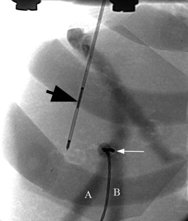
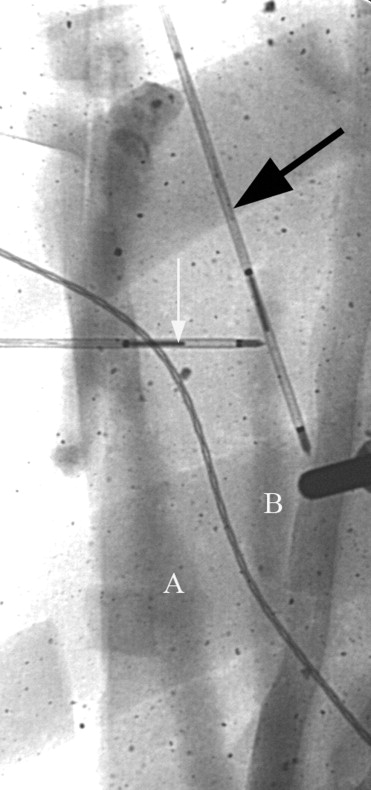
A needle puncture algorithm based on a “free-hand” needle puncture technique for percutaneous intrahepatic portocaval systemic shunt was employed. Preoperatively obtained computed tomographic images were displayed on a graphical user interface and registered with the electromagnetically tracked needle position. The system and procedure was tested on an abdominal torso phantom containing a liver model mounted on a motor-driven platform to simulate respiratory excursion. The liver model featured two hollow tubes to simulate intrahepatic vessels. Registration and respiratory motion tracking was performed using four skin fiducials and a needle fiducial within the liver. Success rates for 15 attempts at simultaneous puncture of the two “vessels” of different luminal diameters guided by the electromagnetic tracking system were recorded.
Results
Successful “vessel” puncture occurred in 0%, 33%, and 53% of attempts for 3-, 5-, and 7-mm diameter “vessels,” respectively. Using a two-dimensional accuracy prediction analysis, predicted accuracy exceeded actual puncture accuracy by 25%–35% for all vessel diameters. Accuracy outcome improved when depth-only errors were omitted from the analysis.
Conclusions
Actual puncture success rate approximates predicted rates for target vessels 5 mm in diameter or greater when depth errors are excluded. Greater accuracy for smaller diameter vessels would be desirable for implementation in a broader range of clinical applications.
Accurate placement of needles within the liver for percutaneous interventions may be accomplished using computed tomography (CT), magnetic resonance imaging (MRI), or ultrasound guidance. Modality-specific limitations include requiring ionizing radiation, nonmagnetically susceptible instruments, or adequate acoustical window without interposed osseous or gas-filled structures. In more complex intrahepatic vascular procedures such as transjugular intrahepatic portocaval systemic shunt (TIPS), shunt creation between portal and hepatic veins is most often accomplished without direct real-time guidance, although planar and three-dimensional ultrasound ( ) and MRI guidance has been reported ( ). Alternatively, the target portal vein can be identified fluoroscopically by several techniques, including wedged hepatic venography using iodinated contrast or carbon dioxide ( ), transhepatic portography, or percutaneous placement of target guidewires or markers in the portal vein ( ).
Respiratory motion interferes with accurate needle placement in static CT-guided interventions, although real-time imaging with ultrasound, CT fluoroscopy, or MRI with breath-hold can help compensate for target excursion with respirations. In an alternative approach, static images would be registered with positional data obtained from an electromagnetic tracking system, allowing the position of electromagnetically tracked instruments to be displayed on the static image. Electromagnetic tracking could be enhanced to track the respiratory related motion of the target organ with retrievable embedded fiducials. The electromagnetic tracking system would then provide 1) real-time location of the tracked needle or instrument and 2) real-time location of the target during the respiratory cycle-related target excursion.
Get Radiology Tree app to read full this article<
Get Radiology Tree app to read full this article<
Get Radiology Tree app to read full this article<
Get Radiology Tree app to read full this article<
Get Radiology Tree app to read full this article<
Get Radiology Tree app to read full this article<
Materials and methods
Determination of Positional Accuracy of the Tracking System
Get Radiology Tree app to read full this article<
Get Radiology Tree app to read full this article<
Get Radiology Tree app to read full this article<
Get Radiology Tree app to read full this article<
Determination of Orientation Accuracy of the Tracking System
Get Radiology Tree app to read full this article<
Accurate Measurement of the Coil Offset
Get Radiology Tree app to read full this article<
Get Radiology Tree app to read full this article<
Phantom Design and Needle Puncture Procedure
Get Radiology Tree app to read full this article<
Get Radiology Tree app to read full this article<
Get Radiology Tree app to read full this article<
Get Radiology Tree app to read full this article<
Get Radiology Tree app to read full this article<
Get Radiology Tree app to read full this article<
Get Radiology Tree app to read full this article<
Get Radiology Tree app to read full this article<
Results
Manufacturer’s Stated System Accuracy
Get Radiology Tree app to read full this article<
Table 1
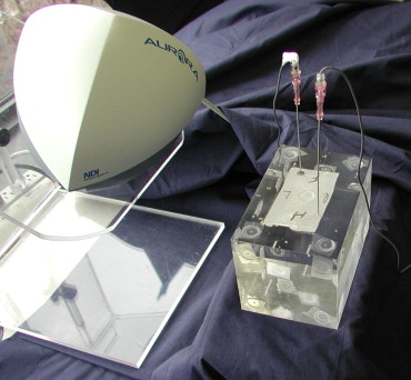
Manufacturer’s Specifications for the Aurora System
Five-Dimensional Sensor Accuracy positional 1–2 mm 3D root mean square ⁎ Accuracy angular 0.5°–1° root mean square ⁎ Sensor Dimensions 0.9 mm diameter × 8 mm Number of sensors 1–10 Measurement rates 20–60 Hz †
Table courtesy of Northern Digital, Inc.
Get Radiology Tree app to read full this article<
Get Radiology Tree app to read full this article<
Get Radiology Tree app to read full this article<
Positional Accuracy
Get Radiology Tree app to read full this article<
Get Radiology Tree app to read full this article<
Table 2
Magnetically Measured Displacement by Robot Axis
x-axis 0–100 mm 100.15 ± 0.10 100 mm to 0 mm 100.46 ± 0.58 y-axis 0–20 mm 19.88 ± 0.10 20 mm to −20 mm 39.28 ± 0.02 −20 mm to 0 mm 19.43 ± 0.04 z-axis 0–20 mm 19.99 ± 0.02 20 mm to −20 mm 40.06 ± 0.05
Get Radiology Tree app to read full this article<
Orientation Accuracy
Get Radiology Tree app to read full this article<
Needle Puncture Experiments
Get Radiology Tree app to read full this article<
Table 3
Needle Puncture Experiment
Incidence Total Frequency 3 mm 5 mm 7 mm Unsuccessful punctures Missed superficial vessel 1 1 2 1 4 Missed deep vessel 2 7 2 9 Missed both vessels 2 2 Depth error only 2 5 7 Missed vessel 1 + depth error 1 1 Missed vessel 2 + depth error 4 1 1 6 Missed vessels 1, 2 + depth error 3 3 Successful punctures 0 5 8 Total passes 15 15 15
Table 4
Predicted vs. Actual Puncture Error Analysis
All Puncture Attempts Total Error (mm) Vessel Diameter (mm) Predicted Success Rates Mean Observed Success Rate Difference Total Attempts Perpendicular Case Parallel Case 4.23 3 0.16 0.42 0.290.00 0.29 15 4.23 5 0.44 0.63 0.540.30 0.24 15 4.23 7 0.86 0.89 0.880.53 0.35 15
All Puncture Attempts excluding Depth Errors Total Error (mm) Vessel Diameter (mm) Predicted Success Rates Mean Observed Success Rate Difference Total Attempts Perpendicular Case Parallel Case 4.23 3 0.16 0.42 0.290.00 0.29 15 4.23 5 0.44 0.63 0.540.39 0.15 13 4.23 7 0.86 0.890.880.80 0.08 10
Get Radiology Tree app to read full this article<
Get Radiology Tree app to read full this article<
Get Radiology Tree app to read full this article<
Discussion
Get Radiology Tree app to read full this article<
Get Radiology Tree app to read full this article<
Get Radiology Tree app to read full this article<
Get Radiology Tree app to read full this article<
Get Radiology Tree app to read full this article<
Get Radiology Tree app to read full this article<
Get Radiology Tree app to read full this article<
Get Radiology Tree app to read full this article<
Get Radiology Tree app to read full this article<
Get Radiology Tree app to read full this article<
Get Radiology Tree app to read full this article<
Get Radiology Tree app to read full this article<
Get Radiology Tree app to read full this article<
Acknowledgments
Get Radiology Tree app to read full this article<
Appendix
Accuracy Prediction Calculations
Get Radiology Tree app to read full this article<
 Open full size image
Get Radiology Tree app to read full this article<
Get Radiology Tree app to read full this article<
Get Radiology Tree app to read full this article<
Get Radiology Tree app to read full this article<
Θ/360 Θ
/
360
to figure out the area of a single sector of the circle.
Get Radiology Tree app to read full this article<
Get Radiology Tree app to read full this article<
B2=A2+C2−(2AC)(cosΘ) B
2
=
A
2
+
C
2
−
(
2
A
C
)
(
cos
Θ
)
Get Radiology Tree app to read full this article<
Get Radiology Tree app to read full this article<
Get Radiology Tree app to read full this article<
Θ=cos−1[(d2−2r2)/2r] Θ
=
cos
−
1
[
(
d
2
−
2
r
2
)
/
2
r
]
Get Radiology Tree app to read full this article<
Get Radiology Tree app to read full this article<
=cos−1[(d2−2r2)/2r]360
cos
−
1
[
(
d
2
−
2
r
2
)
/
2
r
]
360
Get Radiology Tree app to read full this article<
Get Radiology Tree app to read full this article<
=cos−1[(d2−2r2)/2r]πr2180
cos
−
1
[
(
d
2
−
2
r
2
)
/
2
r
]
π
r
2
180
Get Radiology Tree app to read full this article<
Get Radiology Tree app to read full this article<
X2=(d/2)2+r2 X
2
=
(
d
/
2
)
2
+
r
2
Get Radiology Tree app to read full this article<
Get Radiology Tree app to read full this article<
2X=2√((d/2)2+r2) 2
X
=
2
√
(
(
d
/
2
)
2
+
r
2
)
Get Radiology Tree app to read full this article<
Get Radiology Tree app to read full this article<
A=d/2+2√((d/2)2+r2)2 A
=
d
/
2
+
2
√
(
(
d
/
2
)
2
+
r
2
)
2
Get Radiology Tree app to read full this article<
Get Radiology Tree app to read full this article<
1πr2*[cos−1[(d2−2r2)/2r]πr2180+d/2+2√((d/2)2+r2)] 1
π
r
2
*
[
cos
−
1
[
(
d
2
−
2
r
2
)
/
2
r
]
π
r
2
180
+
d
/
2
+
2
√
(
(
d
/
2
)
2
+
r
2
)
]
Get Radiology Tree app to read full this article<
Get Radiology Tree app to read full this article<
A=d2 A
=
d
2
Get Radiology Tree app to read full this article<
Get Radiology Tree app to read full this article<
A(circle)=πr2 A
(
c
i
r
c
l
e
)
=
π
r
2
Get Radiology Tree app to read full this article<
Get Radiology Tree app to read full this article<
d2/πr2 d
2
/
π
r
2
Get Radiology Tree app to read full this article<
Get Radiology Tree app to read full this article<
Get Radiology Tree app to read full this article<
References
1. Rose S.C., Behling C., Roberts A.C., et. al.: Main portal vein access in transjugular intrahepatic portosystemic shunt procedures: use of three-dimensional ultrasound to ensure safety. J Vasc Interv Radiol 2002; 13: pp. 267-273.
2. Roizental M., Kane R.A., Takahashi J., et. al.: Portal vein: US guided localization prior to transjugular intrahepatic portosystemic shunt placement. Radiology 1995; 196: pp. 868-870.
3. Kee S.T., Rhee J.S., Butts K., et. al.: 1999 Gary J. Becker Young Investigator Award. J Vasc Interv Radiol 1999; 10: pp. 529-535.
4. Sheppard D.G., Moss J., Miller M.: Imaging of the portal vein during transjugular portosystemic shunt procedures: a comparison of carbon dioxide and iodinated contrast. Clin Radiol 1998; 53: pp. 448-450.
5. Harman J.T., Reed J.D., Kopecky K.K., et. al.: Localization of the portal vein for transjugular catheterization: percutaneous placement of a metallic marker with real-time US guidance. J Vasc Interv Radiol 1992; 3: pp. 545-547.
6. Fontaine A.B., Verschyl A., Hoffer E., et. al.: Use of CT-guided marking of the portal vein in creation of 150 transjugular intrahepatic portosystemic shunts. J Vasc Interv Radiol 1997; 8: pp. 1073-1077.
7. Magnetic Tracking Technology. Available online at: www.cs.nps.navy.mil/people/faculty/capps/4473/projects/mag-track/full.html . Accessed September 16, 2003.
8. Solomon S.B., Magee C., Acker D.E., et. al.: TIPS placement in swine, guided by electromagnetic real-time needle tip localization displayed on previously acquired 3-D CT. Cardiovasc Intervent Radiol 1999; 22: pp. 411-414.
9. Banovac F., Levy E.B., Lindisch D., et. al.: Feasibility of percutaneous transabdominal portosystemic shunt creation. Surg Radiol Anat 2002; 24: pp. 217-221.
10. Davies S., Hill A., Holmes R., et. al.: Ultrasound quantitation of respiratory organ motion in the upper abdomen. Br J Radiol 1994; 67: pp. 1096-1102.
11. Cleary K., Stoianovici D., Glossop N., et. al.: CT-directed robotic biopsy testbed: motivation and concept. Proc SPIE Med Imaging 2001; 4319: pp. 231-236.
12. The Pivot Alignment Wizard.In NDI 6D Architect Aurora User’s Guide, Revision 1.0.2003.Northern Digital IncOntario, Canada:pp. 55-59.
13. Banovac F., Glossop N., Lindisch D., et. al.: Liver tumor biopsy in a respiring phantom with the assistance of a novel electromagnetic navigation device.Fifth International Conference, Medical Image Computing and Computer Assisted Intervention-MICCAI.2002.SpringerTokyo:pp. 200-207.
14. Banovac F., Glossop N., Jay M., et. al.: Feasibility of image-guided abdominal interventions using a novel magnetic position sensing device in an interventional radiology suite.Computer Assisted Radiology and Surgery (CARS).2002.ElsevierAmsterdam:pp. 1091.
15. Corral G., Cleary K., Tang J., et. al.: Orientation accuracy of a magnetic tracking device for image-guided interventions.Computer Assisted Radiology and Surgery (CARS).2003.ElsevierAmsterdam:pp. 1367.
16. Solomon S.B., White P., Wiener C.M., et. al.: Three-dimensional CT-guided bronchoscopy with a real-time electromagnetic position sensor: a comparison of two image registration methods. Chest 2000; 11: pp. 1783-1787.
17. Bloch R., Fontaine A., Borsa J., et. al.: CT-guided transfemoral portocaval shunt creation. Cardiovasc Intervent Radiol 2001; 24: pp. 106-110.
18. Fitzpatrick J.M., West J.B., Maurer C.R.: Predicting error in rigid-body point-based registration. IEEE Trans Med Imaging 1998; 17: pp. 694-702.
19. Levy E., Cleary K., Banovac F., et. al.: Implementation of a magnetic tracking system for accurate puncture needle guidance.2002. Baltimore, MD, April
20. Davatzikos C., Shen D., Mohamed A., et. al.: A framework for predictive modeling of anatomical deformations. IEEE Trans Med Imaging 2001; 20: pp. 836-843.