
Rationale and Objectives
To investigate the ability of an intravascular magnetic resonance (MR) loopless antenna to reduce the radiofrequency shielding of a vascular stent during signal reception as a way to improve the visualization of the in-stent lumen.
Methods and Materials
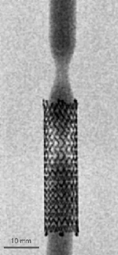
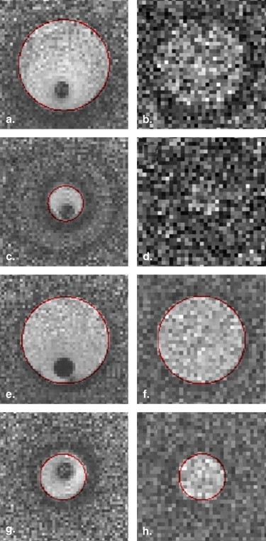
Using a balanced steady-state free-precession (bSSFP) sequence and a dedicated vascular phantom, the signal-to-noise ratio (SNR) inside the lumen of a stent is evaluated as a function of the nominal flip angle and compared with the results obtained for a reference vessel without a stent. All experiments are performed using successively an intravascular loopless antenna and surface arrays coils. Using an optimized protocol, in vitro in-stent restenosis visualization and quantification experiments are performed to evaluate the validity of an approach using an intravascular antenna and cross-sectional images to depict a vascular lesion inside a stent.
Results
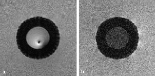
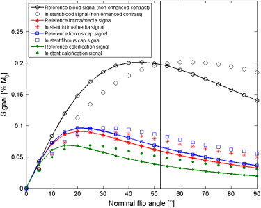
The use of a loopless antenna effectively eliminates the radiofrequency shielding effect of the stent during signal reception. Furthermore, using a bSSFP sequence with a carefully chosen nominal flip angle, an equally good blood SNR can be obtained inside and outside the stent. Results of in vitro in-stent restenosis quantification measurements using the proposed method illustrate the benefits arising from the use of the intravascular antenna.
Conclusion
In the perspective of MR-guided vascular interventions, the presented results illustrate that the use of an intravascular antenna can significantly facilitate imaging inside a vascular stent. Potential applications include the monitoring of stent deployment as well as visualization and quantification of in-stent restenosis during an intervention.
Vascular stents are widely used during revascularization procedures to improve the short- and long-term success rate of the intervention . However, metallic implants such as vascular stents are also known to produce susceptibility and radiofrequency (RF) shielding artefacts that can considerably hinder the depiction of the stent lumen during magnetic resonance angiography (MRA) and therefore reduce the validity of this approach for a subsequent visualization of the vessel. For instance, a recognized complication of a revascularization procedure using a vascular implant is in-stent restenosis , and the assessment and quantification of this potential problem requires a careful follow-up inspection of the in-stent lumen that can be hindered by the artefacts created by the stent itself. Proposed solutions to increase the luminal depiction inside the stent during MRA include the use of specially designed inductively coupled or artefact-free stents and the employment of an angiography sequence with an increased flip angle .
Along with the development of MRA as a diagnostic tool, several developments toward the execution of endovascular interventional therapeutic procedures under MRA guidance have been made. In comparison to the standard clinical setup using X-rays, magnetic resonance imaging offers a complete elimination of the use of ionizing radiation, a reduction in the use of nephrotoxic contrast agents, functional and anatomical information in three dimensions, and an appreciably improved contrast between soft tissues. However, in the case of a procedure involving the deployment of a stent or a previously implanted stent, these benefits can potentially be locally canceled by the reduction of the lumen depiction caused by the stent.
Get Radiology Tree app to read full this article<
Get Radiology Tree app to read full this article<
Get Radiology Tree app to read full this article<
Materials and methods
Background MR Physics Theory
Get Radiology Tree app to read full this article<
Get Radiology Tree app to read full this article<
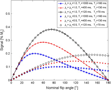
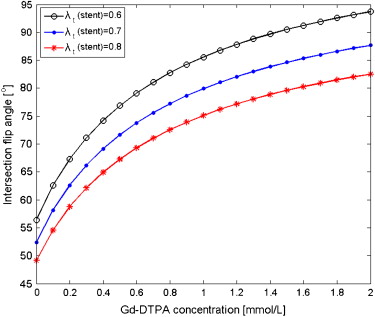
SbSSFP=λr(r→)M0e−TR/T2√(1−e−TR/T1)sin(λt(r→)α)1−(e−TR/T1−e−TR/T2)cos(λt(r→)α)−e−TR/T1e−TR/T2, S
b
S
S
F
P
=
λ
r
(
r
→
)
M
0
e
−
T
R
/
T
2
(
1
−
e
−
T
R
/
T
1
)
sin
(
λ
t
(
r
→
)
α
)
1
−
(
e
−
T
R
/
T
1
−
e
−
T
R
/
T
2
)
cos
(
λ
t
(
r
→
)
α
)
−
e
−
T
R
/
T
1
e
−
T
R
/
T
2
,
where α is the nominal flip angle applied and M 0 is the equilibrium magnetization. The λr(r→) λ
r
(
r
→
) and λt(r→) λ
t
(
r
→
) parameters indicate, respectively, the reception and transmission efficiency of the system. For example, the condition λr(r→o) λ
r
(
r
→
o
) = λt(r→o) λ
t
(
r
→
o
) = 1 implies that the effective flip angle at the position r→=r→0 r
→
=
r
→
0 will be equal to the nominal flip angle and that the signal from that point will be received with a 100% relative efficiency. In the case of a voxel located inside the lumen of a vascular stent and imaged using external coils for both transmission and reception, it can be expected that the λr(r→) λ
r
(
r
→
) and λt(r→) λ
t
(
r
→
) efficiency parameters will be significantly lower than 1, as a result of the RF shielding effect of the stent itself. Effectively, values between 0.38 and 0.57 were reported for an experiment using a fast spoiled gradient echo sequence for nitinol stents placed parallel to the main magnetic of 1.5 T scanner .
Get Radiology Tree app to read full this article<
Get Radiology Tree app to read full this article<
Get Radiology Tree app to read full this article<
RF Shielding Evaluation and Sequence Optimization
Get Radiology Tree app to read full this article<
Get Radiology Tree app to read full this article<
In-stent Restenosis Visualization
Get Radiology Tree app to read full this article<
Get Radiology Tree app to read full this article<
Get Radiology Tree app to read full this article<
Get Radiology Tree app to read full this article<
Results
RF Shielding Evaluation and Sequence Optimization
Get Radiology Tree app to read full this article<
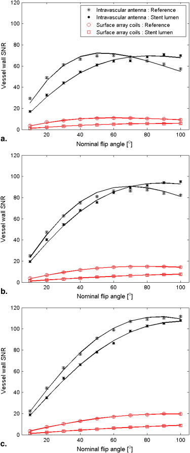
Table 1
Relaxation Times and Ratios of In-stent/reference Reception and Transmission Efficiencies for the Intravascular Antenna and the Surface Array Coils
Intravascular Antenna Surface Array Coils Gd-DTPA (mmol/L) T 1 (ms) ∗ T 2 (ms) ∗ λr(stent)Unknown node type: cross_refλr(ref) λ
r
(
s
t
e
n
t
)
Unknown node type: cross_ref
λ
r
(
r
e
f
) λt(stent)Unknown node type: cross_refλt(ref) λ
t
(
s
t
e
n
t
)
Unknown node type: cross_ref
λ
t
(
r
e
f
) λr(stent)Unknown node type: cross_refλr(ref) λ
r
(
s
t
e
n
t
)
Unknown node type: cross_ref
λ
r
(
r
e
f
) λt(stent)Unknown node type: cross_refλt(ref) λ
t
(
s
t
e
n
t
)
Unknown node type: cross_ref
λ
t
(
r
e
f
) 0 841 (833–849) 138 (133–143) 0.96 (0.92–1.00) 0.65 (0.59–0.71) 0.52 (0.50–0.54) 0.60 (0.56–0.64) 0.36 348 (345–351) 110 (106–114) 1.03 (1.00–1.06) 0.78 (0.73–0.83) 0.53 (0.50–0.56) 0.58 (0.53–0.63) 1.80 110 (107–113) 63 (59–67) 0.96 (0.94–0.98) 0.74 (0.70–0.78) 0.50 (0.48–0.52) 0.63 (0.60–0.66)
Get Radiology Tree app to read full this article<
Get Radiology Tree app to read full this article<
Get Radiology Tree app to read full this article<
Get Radiology Tree app to read full this article<
Get Radiology Tree app to read full this article<
Get Radiology Tree app to read full this article<
Get Radiology Tree app to read full this article<
Get Radiology Tree app to read full this article<
Get Radiology Tree app to read full this article<
In-stent Restenosis Visualization
Get Radiology Tree app to read full this article<
Get Radiology Tree app to read full this article<
Get Radiology Tree app to read full this article<
Table 2
Stenosis Quantification Results for the Reference and In-stent Stenoses
Theoretical Value Estimated Value ∗ Intravascular Antenna Estimated Value ∗ Surface Array Coils In-stent stenosis 90% 85% (82%–88%) — Reference stenosis 75% 72% (67%–77%) 73% (67%–79%)
Get Radiology Tree app to read full this article<
Get Radiology Tree app to read full this article<
Discussion
Get Radiology Tree app to read full this article<
Get Radiology Tree app to read full this article<
Get Radiology Tree app to read full this article<
Get Radiology Tree app to read full this article<
Get Radiology Tree app to read full this article<
Get Radiology Tree app to read full this article<
Get Radiology Tree app to read full this article<
Get Radiology Tree app to read full this article<
References
1. Van de Ven P.J.G., Kaatee R., Beutler J.J., et. al.: Arterial stenting and balloon angioplasty in ostial atherosclerotic renovascular disease: a randomised trial. Lancet 1999; 353: pp. 282-286.
2. Bartels L.W., Bakker C.J.G., Viergever M.A.: Improved lumen visualization in metallic vascular implants by reducing RF artifacts. Magnet Reson Med 2002; 47: pp. 171-180.
3. Wang Y., Truong T.N., Yen C., et. al.: Quantitative evaluation of susceptibility and shielding effects of nitinol, platinum, cobalt-alloy, and stainless steel stents. Magnet Reson Med 2003; 49: pp. 972-976.
4. Graf H., Steidle G., Lauer U.A., et. al.: RF enhancement and shielding in MRI caused by conductive implants: dependence on electrical parameters for a tube model. Med Phys 2005; 32: pp. 337-342.
5. Vignali C., Bargellini I., Lazzereschi M., et. al.: Predictive factors of in-stent restenosis in renal artery stenting: a retrospective analysis. Cardiovasc Interv Radiol 2005; 28: pp. 296-302.
6. Quick H.H., Kuelh H., Kaiser G., et. al.: Inductively coupled stent antennas in MRI. Magnet Reson Med 2002; 48: pp. 781-790.
7. Spuentrup E., Ruebben A., Suber M., et. al.: Metallic renal artery MR imaging stent: artifact-free lumen visualization with projection and standard renal MR angiography. Radiology 2003; 227: pp. 897-902.
8. Elgort D.R., Hillenbrand C.M., Zhang S., et. al.: Image-guided and -monitored renal artery stenting using only MRI. J Magnet Reson Imaging 2006; 23: pp. 619-627.
9. Bock M., Wacker F.K.: MR-guided intravascular interventions: techniques and applications. J Magnet Reson Imaging 2008; 27: pp. 326-338.
10. Larose E., Kinlay S., Selwyn A.P., et. al.: Improved characterization of atherosclerotic plaques by gadolinium contrast during intravascular magnetic resonance imaging of human arteries. Atherosclerosis 2008; 196: pp. 915-925.
11. Hillenbrand C.M., Jesberger J.A., Wong E.Y., et. al.: Toward rapid high resolution in vivo intravascular MRI: evaluation of vessel wall conspicuity in a porcine model using multiple imaging protocols. J Magnet Reson Imaging 2006; 23: pp. 135-144.
12. Scheffler K.: On the transient phase of balanced SSFP sequences. Magnet Reson Med 2003; 49: pp. 781-783.
13. Strich G., Hagan P.L., Gerber K.H., et. al.: Tissue distribution and magnetic resonance spin lattice relaxation effects of gadolinium-DTPA. Radiology 1985; 154: pp. 723-726.
14. Westenberg J.J.M., Wasser M.N.J.M., van der Geest R.J., et. al.: Gadolinium contrast-enhanced three-dimensional MRA of peripheral arteries with multiple bolus injection: scan optimization in vitro and in vivo. International J Cardiac Imaging 1999; 15: pp. 161-173.
15. Ocali O., Atalar E.: Intravascular magnetic resonance imaging using a loopless catheter antenna. Magnet Reson Med 1997; 37: pp. 112-118.
16. Cloutier G., Soulez G., Qanadli S.D., et. al.: A multimodality vascular imaging phantom with fiducial markers visible in DSA, CTA, MRA, and ultrasound. Med Phys 2004; 31: pp. 1424-1433.
17. Létourneau-Guillon L., Soulez G., Beaudoin G., et. al.: CT and MR imaging of nitinol stents with radiopaque distal markers. J Vasc Interv Radiol 2004; 15: pp. 615-624.
18. Boussion N., Soulez G., de Guise J.A., et. al.: Geometrical accuracy and fusion of multimodal vascular images: a phantom study. Med Phys 2004; 31: pp. 1434-1443.
19. Gilbert G., Soulez G., Beaudoin G.: Comparative evaluation of the geometrical accuracy of intravascular magnetic resonance imaging: a phantom study. Acad Radiol 2009; 16: pp. 988-996.
20. Dietrich O., Heiland S., Sartor S.K.: Noise correction for the exact determination of apparent diffusion coefficients at low SNR. Magnet Reson Med 2001; 45: pp. 448-453.
21. Merkle E.M., Dale B.M., Barboriak D.P.: Gain in signal-to-noise for first-pass contrast-enhanced abdominal MR angiography at 3 Tesla over standard 1.5 Tesla: prediction with a computer model. Acad Radiol 2007; 14: pp. 795-803.
22. Sharma R., Singh R.B., Gupta R.K.: A segmentation method for carotid artery atherosclerosis plaque for MRI contrast and MRI features, oxidative stress markers in coronary and carotid plaque. IEEE Symposium on Computer-Based Medical Systems 2003; 16: pp. 323-328.
23. Omary R.A., Schirf B.E., Green J.D., et. al.: Catheter-directed MR angiography and cross-sectional imaging for the assessment of renal artery stenosis. J Vasc Interv Radiol 2005; 16: pp. 255-260.
24. Hillenbrand C.M., Elgort D.R., Wong E.Y., et. al.: Active device tracking and high-resolution intravascular MRI using a novel catheter-based, opposed-solenoid phased array coil. Magnet Reson Med 2004; 51: pp. 668-675.
25. Quick H.H., Ladd M.E., Zimmermann-Paul G.G., et. al.: Single-loop coil concepts for intravascular magnetic resonance imaging. Magnet Reson Med 1999; 41: pp. 751-758.
26. Anderson K.J.T., Leung G., Dick A.J., et. al.: Forward-looking intravascular orthogonal-solenoid coil for imaging and guidance in occlusive arterial disease. Magnet Reson Med 2008; 60: pp. 489-495.
27. Konings M.K., Bartels L.W., Smits H.F.M., et. al.: Heating around intravascular guidewires by resonating RF waves. J Magnet Reson Imaging 2000; 12: pp. 79-85.
28. Susil R.C., Yeung C.J., Atalar E.: Intravascular extended sensitivity (IVES) MRI antennas. Magnet Reson Med 2003; 50: pp. 383-390.