
Rationale and Objectives
The study aimed to evaluate in vitro stent lumen visibility of coronary stents in a second- and third-generation dual-source computed tomography (CT) system at 100 and 120 kVp tube potential.
Materials and Methods
Twenty-six coronary stents ranging from 2.25 to 4.0 mm in diameter were implanted in a coronary vessel phantom. Scans were performed at 100 and 120 kVp tube potential. Evaluation was performed using a medium-sharp kernel in both systems (B46f in the second-generation and Bv49 in the third-generation model) and a sharp (Bv59) convolution kernel optimized for vascular imaging in the third-generation CT.
Results
The median visible stent lumen diameter in the second-generation system was higher at 120 kVp with a median of 62.0% compared to 56.3% at 100 kVp ( P < 0.001). The median visible diameter in the third-generation system was significantly higher applying the Bv49 kernel with 66.7% at 120 kVp and 61.1% at 100 kVp (both P < 0.001). When applying the Bv59 kernel, visible stent lumen further increased to 69.3% at 120 kVp and 66.7% at 100 kVp. Additionally, stent lumen was assessed using full width at half maximum, resulting in a comparable increase in luminal diameter at corresponding tube potential.
Conclusions
Third-generation dual-source CT provides superior stent lumen visibility at equivalent tube potential and at reduced tube potential of 100 kVp when compared to 120 kVp in a second-generation system, at least when manually assessed.
Introduction
An estimated 492,000 patients underwent percutaneous coronary intervention in the United States in 2010 . In-stent restenosis is a major limitation of percutaneous coronary intervention, and although its incidence decreased with the advent of drug-eluting stents it remains in the range of 3%–20% . Several thousand coronary angiographies are performed each year to exclude in-stent restenosis, exposing the patient to the minor but definite risks of an invasive procedure. Thus, a noninvasive method for diagnosis or exclusion of in-stent restenosis is desirable.
Yet various stent materials cause different magnitudes of x-ray attenuation, leading to beam hardening and blooming artifacts, and eventually hindering stent lumen assessment. Previous studies have shown that computed tomographic angiography (CTA) might be an appropriate tool for visualization of coronary stents. However, image quality is strongly dependent on the material and architecture of the stents reviewed, as well as the technical capabilities of the computed tomography (CT) system used for evaluation .
Get Radiology Tree app to read full this article<
Get Radiology Tree app to read full this article<
Get Radiology Tree app to read full this article<
Materials and Methods
Experimental Setup
Get Radiology Tree app to read full this article<
Table 1
Stent Characteristics
Number Manufacturer Name Material Coating Diameter (mm) Length (mm) Strut Thickness (mm) 1 Abbott JOSTENT Graftmaster Stainless steel + PTFE None 3.0 16 0.300 (wall thickness) 2 Abbott Multilink Vision Cobalt-chromium alloy None 3.0 23 0.081 3 Abbott Xience Pro Cobalt-chromium alloy Everolimus 3.0 15 0.081 4 Biotronik Orsiro Cobalt-chromium alloy Poly-L-lactic acid (PLLA) polymer, Sirolimus 2.25 18 0.060 5 Biotronik Orsiro Cobalt-chromium alloy Poly-L-lactic acid (PLLA) polymer, Sirolimus 2.5 13 0.060 6 Biotronik Orsiro Cobalt-chromium alloy Poly-L-lactic acid (PLLA) polymer, Sirolimus 2.75 13 0.060 7 Biotronik Orsiro Cobalt-chromium alloy Poly-L-lactic acid (PLLA) polymer, Sirolimus 3.0 18 0.060 8 Biotronik Orsiro Cobalt-chromium alloy Poly-L-lactic acid (PLLA) polymer, Sirolimus 3.5 26 0.060 9 Biotronik Orsiro Cobalt-chromium alloy Poly-L-lactic acid (PLLA) polymer, Sirolimus 4.0 15 0.060 10 Biotronik PRO-Kinetic Energy Cobalt-chromium alloy PROBIO Amorphous Silicon Carbide Coating 3.0 20 0.060 11 Boston Scientific Omega Platinum-chromium alloy None 3.0 16 0.081 12 Boston Scientific TAXUS Liberté Stainless steel None 3.0 38 0.100 13 Braun Coroflex Blue Cobalt-chromium alloy None 3.0 19 0.065 14 Cordis Cypher Stainless steel Sirolimus 3.0 28 0.140 15 Medtronic Resolute RX Cobalt-chromium alloy Zotarolimus 3.0 18 0.091 16 Medtronic Resolute Integrity RX Cobalt-chromium alloy Zotarolimus 3.5 26 0.091 17 Medtronic Resolute Integrity RX Cobalt-chromium alloy Zotarolimus 4.0 34 0.091 18 Medtronic Integrity RX Cobalt-chromium alloy Zotarolimus 2.25 30 0.091 19 Medtronic Integrity BMS Cobalt-chromium alloy None 2.5 26 0.091 20 Medtronic Integrity RX Cobalt-chromium alloy None 2.75 30 0.091 21 Medtronic Integrity RX Cobalt-chromium alloy None 3.0 22 0.091 22 Medtronic Integrity RX Cobalt-chromium alloy None 3.5 26 0.091 23 Medtronic Integrity RX Cobalt-chromium alloy None 4.0 15 0.091 24 OrbusNeich Genous Stainless steel Anti-hCD34 antibody 3.0 18 0.081 25 Terumo Kaname Cobalt-chromium alloy None 3.0 28 0.080 26 Terumo Nobori Stainless steel Poly-L-lactic acid (PLLA) polymer, Biolimus A9 3.0 28 0.120
Get Radiology Tree app to read full this article<
Get Radiology Tree app to read full this article<
Get Radiology Tree app to read full this article<
CT Scan Protocol
Get Radiology Tree app to read full this article<
Get Radiology Tree app to read full this article<
Get Radiology Tree app to read full this article<
Data Reconstruction
Get Radiology Tree app to read full this article<
Get Radiology Tree app to read full this article<
Image Analysis
Get Radiology Tree app to read full this article<
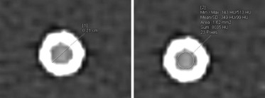
Get Radiology Tree app to read full this article<
Statistical Analysis
Get Radiology Tree app to read full this article<
Results
Get Radiology Tree app to read full this article<
Table 2
Visible Stent Lumen Diameters, In-stent Attenuation, and Noise at 100 and 120 kVp Tube Voltage
SOMATOM Definition Flash SOMATOM Force B46f–100 kVp B46f–120 kVp Bv49–100 kVp Bv49–120 kVp Bv59–100 kVp Bv59–120 kVp Visible diameter (%) 56.3 62.0 61.1 66.7 66.7 69.3 (49.7–60.3; 36–70) (55.9–64.4; 46–77) (55.6–64.5; 40–71) (64.4–71.4; 49–78) (64.4–71.6; 44–80) (66.0–75.6; 50–81) Attenuation (HU) 574 460 575 484 542 457 (552–605; 519–777) (453–490; 442–647) (558–597; 508–697) (471–498; 417–664) (535–569; 475–600) (414–493; 305–550) Noise (HU) 27.5 21.5 34.0 26.0 39.0 35.7 (24.8–29.0; 21–34) (19.8–23.0; 15–26) (32.8–35.0; 26–37) (24.8–27.0; 20–29) (37.8–40.0; 30–42) (28.2–36.7; 26–46)
Values provided as median, interquartile range, and range.
Get Radiology Tree app to read full this article<
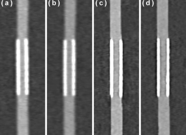
Manual Measurements
Second-generation Dual-source CT
Get Radiology Tree app to read full this article<
Get Radiology Tree app to read full this article<
Third-generation Dual-source CT
Get Radiology Tree app to read full this article<
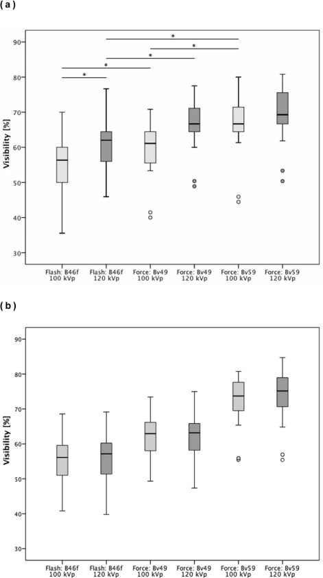
Get Radiology Tree app to read full this article<
Get Radiology Tree app to read full this article<
Get Radiology Tree app to read full this article<
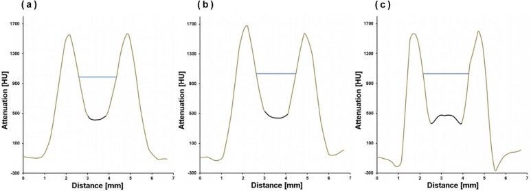
Semi-automatic Evaluation Using FWHM
Get Radiology Tree app to read full this article<
Get Radiology Tree app to read full this article<
Discussion
Get Radiology Tree app to read full this article<
Get Radiology Tree app to read full this article<
Get Radiology Tree app to read full this article<
Get Radiology Tree app to read full this article<
Get Radiology Tree app to read full this article<
Get Radiology Tree app to read full this article<
Get Radiology Tree app to read full this article<
Limitations
Get Radiology Tree app to read full this article<
Get Radiology Tree app to read full this article<
Get Radiology Tree app to read full this article<
Get Radiology Tree app to read full this article<
Conclusions
Get Radiology Tree app to read full this article<
References
1. Go A.S., Mozaffarian D., Roger V.L., et. al.: Heart disease and stroke statistics—2014 update: a report from the American Heart Association. Circulation 2014; 129: pp. e28-e292.
2. Dangas G.D., Claessen B.E., Caixeta A., et. al.: In-stent restenosis in the drug-eluting stent era. J Am Coll Cardiol 2010; 56: pp. 1897-1907.
3. Maintz D., Seifarth H., Raupach R., et. al.: 64-slice multidetector coronary CT angiography: in vitro evaluation of 68 different stents. Eur Radiol 2006; 16: pp. 818-826.
4. Maintz D., Burg M.C., Seifarth H., et. al.: Update on multidetector coronary CT angiography of coronary stents: in vitro evaluation of 29 different stent types with dual-source CT. Eur Radiol 2009; 19: pp. 42-49.
5. Sun Z., Almutairi A.M.D.: Diagnostic accuracy of 64 multislice CT angiography in the assessment of coronary in-stent restenosis: a meta-analysis. Eur J Radiol 2010; 73: pp. 266-273.
6. Kumbhani D.J., Ingelmo C.P., Schoenhagen P., et. al.: Meta-analysis of diagnostic efficacy of 64-slice computed tomography in the evaluation of coronary in-stent restenosis. Am J Cardiol 2009; 103: pp. 1675-1681.
7. Sheth T., Dodd J.D., Hoffmann U., et. al.: Coronary stent assessability by 64 slice multi-detector computed tomography. Catheter Cardiovasc Interv 2007; 69: pp. 933-938.
8. Pugliese F., Weustink A.C., Van Mieghem C., et. al.: Dual source coronary computed tomography angiography for detecting in-stent restenosis. Heart 2008; 94: pp. 848-854.
9. Donati O.F., Burg M.C., Desbiolles L., et. al.: High-pitch 128-slice dual-source CT for the assessment of coronary stents in a phantom model. Acad Radiol 2010; 17: pp. 1366-1374.
10. Rief M., Zimmermann E., Stenzel F., et. al.: Computed tomography angiography and myocardial computed tomography perfusion in patients with coronary stents: prospective intraindividual comparison with conventional coronary angiography. J Am Coll Cardiol 2013; 62: pp. 1476-1485.
11. Roura G., Gomez-Lara J., Ferreiro J.L., et. al.: Multislice CT for assessing in-stent dimensions after left main coronary artery stenting: a comparison with three dimensional intravascular ultrasound. Heart 2013; 99: pp. 1106-1112.
12. André F., Müller D., Korosoglou G., et. al.: In-vitro assessment of coronary artery stents in 256-multislice computed tomography angiography. BMC Res Notes 2014; 7: pp. 38.
13. Eisentopf J., Achenbach S., Ulzheimer S., et. al.: Low-dose dual-source CT angiography with iterative reconstruction for coronary artery stent evaluation. JACC Cardiovasc Imaging 2013; 6: pp. 458-465.
14. Gassenmaier T., Petri N., Allmendinger T., et. al.: Next generation coronary CT angiography: in vitro evaluation of 27 coronary stents. Eur Radiol 2014; 24: pp. 2953-2961.
15. Renker M., Ramachandra A., Schoepf U.J., et. al.: Iterative image reconstruction techniques: applications for cardiac CT. J Cardiovasc Comput Tomogr 2011; 5: pp. 225-230.
16. Andreini D., Pontone G., Bartorelli A.L., et. al.: Comparison of feasibility and diagnostic accuracy of 64-slice multidetector computed tomographic coronary angiography versus invasive coronary angiography versus intravascular ultrasound for evaluation of in-stent restenosis. Am J Cardiol 2009; 103: pp. 1349-1358.
17. Min J.K., Swaminathan R.V., Vass M., et. al.: High-definition multidetector computed tomography for evaluation of coronary artery stents: comparison to standard-definition 64-detector row computed tomography. J Cardiovasc Comput Tomogr 2009; 3: pp. 246-251.
18. Andreini D., Pontone G., Mushtaq S., et. al.: Coronary in-stent restenosis: assessment with CT coronary angiography. Radiology 2012; 265: pp. 410-417.
19. Seifarth H., Ozgün M., Raupach R., et. al.: 64- versus 16-slice CT angiography for coronary artery stent assessment: in vitro experience. Invest Radiol 2006; 41: pp. 22-27.