
Rationale and Objectives
To retrospectively investigate the effect of flip angle (FA) and k -space sampling on the performance of dynamic contrast-enhanced (DCE-) magnetic resonance imaging (MRI) breast sequences.
Materials and Methods
Five DCE-MRI breast sequences were evaluated (10°, 14°, and 18° FAs; radial or linear k -space sampling), with 7–10 patients in each group ( n = 45). All sequences were compliant with current technical breast screening guidelines. Contrast agent (CA) uptake curves were constructed from the right mammary artery for each examination. Maximum relative enhancement, E max , and time-to-peak enhancement, T max , were measured and compared between protocols (analysis of variance and Mann–Whitney). For each sequence, calculated values of maximum relative enhancement, E calc , were derived from the Bloch equations and compared to E max . Fat suppression performance (residual bright fat and chemical shift artifact) was rated for each examination and compared between sequences (Fisher exact tests).
Results
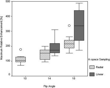
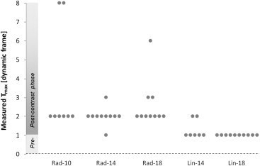
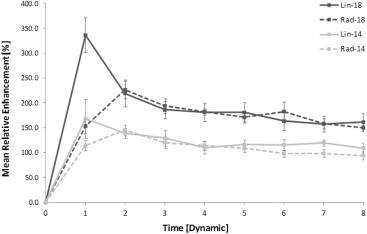
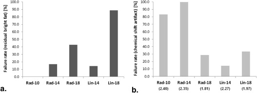
Significant differences were identified between DCE-MRI sequences. E max increased significantly at higher FAs and with linear k -space sampling ( P < .0001; P = .001). Radial protocols exhibited greater T max than linear protocols at FAs of both 14° ( P = .025) and 18° ( P < .0001), suggesting artificially flattened uptake curves. Good correlation was observed between E calc and E max ( r = 0.86). Fat suppression failure was more pronounced at an FA of 18° ( P = .008).
Conclusions
This retrospective approach is validated as a tool to compare and optimize breast DCE-MRI sequences. Alterations in FA and k -space sampling result in significant differences in CA uptake curve shape which could potentially affect diagnostic interpretation. These results emphasize the need for careful parameter selection and greater standardization of breast DCE-MRI sequences.
In the evaluation of breast tumors, the Breast Imaging Reporting and Data System lexicon classifies both lesion morphology and the pattern of contrast agent (CA) uptake with time . Dynamic contrast-enhanced (DCE) magnetic resonance imaging (MRI) is used to increase the specificity of breast MRI examinations, through evaluation of the kinetic behavior of CA uptake . Enhancement curves may demonstrate persistent, plateau, or wash-out behaviors of signal intensity across the dynamic series, where a wash-out of signal intensity is often indicative of malignancy . With smaller lesions in which morphology is indeterminate, this evaluation of CA kinetics becomes increasingly important in diagnosis.
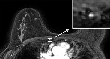
Reliable classification of CA uptake curves requires rapid T 1 -weighted pulse sequences to be designed to provide image intensity directly proportional to CA concentration over the range of expected T 1 values. Effective fat suppression is also required to facilitate the assessment of small lesions. Accurate evaluation and standardization of sequence performance is particularly important because differences across magnetic resonance (MR) systems and sequences can significantly affect sensitivity for detecting lesions . However, the accuracy of sequence assessment with test objects is limited: spatial variations in the B 1 field can hinder verification of image intensity dependence on T 1 and the flip angle (FA) applied to a test object may not accurately represent clinical examinations. In addition, variability in patient size and shape and differences in patient circulation affect T 1 values after intravenous CA administration. An assessment of the impact of sequence parameter changes on the diagnostic capability of an examination would therefore be invaluable. As the internal mammary artery provides a source of arterial enhancement in the examination field of view, we used it to construct signal intensity versus time curves retrospectively and compared these curves between patients examined with breast DCE-MRI sequences of varying FAs and k -space sampling patterns. We simultaneously assessed the effect of these parameters on fat suppression performance. Every sequence evaluated was used in clinical practice and was therefore compliant with current technical breast screening guidelines . Sequences with different k -space sampling coverage pattern and FA were modeled to validate experimental results.
Materials and methods
MRI Protocols
Get Radiology Tree app to read full this article<
Table 1
Summary of MRI Protocols
System Philips 1.5 T Intera Philips 1.5 T Achieva Philips 1.5 T Intera Group Notation Rad-10 Rad-14 Rad-18 Lin-14 Lin-18 Sample size 8 10 10 7 10 Flip angle 10° 14° 18° 14° 18°K -space sampling Radial Radial Radial Linear Linear TR/TE, ms 5.10/2.39 5.10/2.35 3.94/1.81 4.58/2.27 4.10/1.97 Number of echoes per shot 100 100 60 100 100 Slice thickness, mm 2.5 2.5 2.0 2.0 2.0 In-plane resolution, mm 0.63 0.63 1.25 1.25 1.25
MRI, magnetic resonance imaging; TE, echo time; TR, repetition time.
Get Radiology Tree app to read full this article<
Theoretical Calculation of Relative Enhancement and Fat Suppression Efficiency
Get Radiology Tree app to read full this article<
Get Radiology Tree app to read full this article<
Analysis of Dynamic Contrast-Enhanced Examinations
Get Radiology Tree app to read full this article<
Get Radiology Tree app to read full this article<
Get Radiology Tree app to read full this article<
Evaluation of Fat Suppression
Get Radiology Tree app to read full this article<
Data Analysis
Get Radiology Tree app to read full this article<
Get Radiology Tree app to read full this article<
Results
Calculation of Relative Enhancement and Fat Suppression Efficiency
Get Radiology Tree app to read full this article<
Table 2
Values of E calc with Mean and Standard Deviation of Measured E max
System Philips 1.5 T Intera Philips 1.5 T Achieva Philips 1.5 T Intera Group Rad-10 Rad-14 Rad-18 Lin-14 Lin-18E calc , % 220 348 484 367 486E max , % 113 ± 32 146 ± 35 223 ± 52 196 ± 63 336 ± 112
E calc , calculated maximum relative enhancement; E max , measured maximum relative enhancement.
Get Radiology Tree app to read full this article<
Get Radiology Tree app to read full this article<
Get Radiology Tree app to read full this article<
Analysis of Dynamic Contrast-Enhanced Examinations
Get Radiology Tree app to read full this article<
Get Radiology Tree app to read full this article<
Get Radiology Tree app to read full this article<
Get Radiology Tree app to read full this article<
Get Radiology Tree app to read full this article<
Get Radiology Tree app to read full this article<
Get Radiology Tree app to read full this article<
Fat Suppression Evaluation
Get Radiology Tree app to read full this article<
Table 3
Evaluation of Fat Suppression Performance Across the Patient Groups
Group Unsuppressed Fat Chemical Shift Artifact Fat Suppression Successful Fat Suppression Unsuccessful Total Fat Suppression Successful Fat Suppression Unsuccessful Total Rad-10 6 (100.0) 0 (0.0) 6 1 (16.7) 5 (83.3) 6 Rad-14 5 (83.3) 1 (16.7) 6 0 (0.0) 6 (100.0) 6 Rad-18 4 (57.1) 3 (42.9) 7 5 (71.4) 2 (28.6) 7 Lin-14 6 (85.7) 1 (14.3) 7 6 (85.7) 1 (14.3) 7 Lin-18 1 (11.1) 8 (88.9) 9 6 (66.7) 3 (33.3) 9 Total 35 35
Get Radiology Tree app to read full this article<
Regions of Unsuppressed Fat
Get Radiology Tree app to read full this article<
Chemical Shift Artifact
Get Radiology Tree app to read full this article<
Discussion
Get Radiology Tree app to read full this article<
Get Radiology Tree app to read full this article<
Get Radiology Tree app to read full this article<
Get Radiology Tree app to read full this article<
Get Radiology Tree app to read full this article<
Get Radiology Tree app to read full this article<
Get Radiology Tree app to read full this article<
Get Radiology Tree app to read full this article<
Get Radiology Tree app to read full this article<
Get Radiology Tree app to read full this article<
Get Radiology Tree app to read full this article<
References
1. BI-RADS: MRI Breast Imaging Reporting and Data System. BI-RADS At.2003.American College of RadiologyReston, VA
2. Mahoney M.C., Gatsonis C., Hanna L., et. al.: Positive predictive value of BI-RADS MR imaging. Radiology 2012; 264: pp. 51-58.
3. Heywang-Köhbrunner S., Bick U., Bradley W., et. al.: International investigation of breast MRI: results of a multi-centre study (11 sites) concerning diagnostic parameters for contrast-enhanced MRI based on 519 histopathologically correlated lesions. Eur Radiol 2001; 11: pp. 531-546.
4. Schnall M.D., Blume J., Bluemke D.A., et. al.: Diagnostic architectural and dynamic features at breast MR imaging: multicenter study. Radiology 2006; 238: pp. 42-53.
5. Kuhl C.K., Mielcareck P., Klaschik S., et. al.: Dynamic breast MR imaging: are signal intensity time course data useful for differential diagnosis of enhancing lesions?. Radiology 1999; 211: pp. 101-110.
6. Jansen S.A., Shimauchi A., Zak L., et. al.: Kinetic curves of malignant lesions are not consistent across MRI systems: need for improved standardization of breast dynamic contrast-enhanced MRI acquisition. Am J Roentgenol 2009; 193: pp. 832-839.
7. Azlan C.A., Ahearn T.S., Di Giovanni P., et. al.: Quantification techniques to minimize the effects of native T1 variation and B1 inhomogeneity in dynamic contrast-enhanced MRI of the breast at 3 T. Magn Reson Med 2012; 67: pp. 531-540.
8. Clayton D, Davison C, Bailey C, et al. Technical guidelines for magnetic resonance imaging for the surveillance of women at higher risk of developing breast cancer (NHSBSP Publication No 68) p. 1–31.
9. 2012.American College of RadiologyReston, VApp. 1-16.
10. Bloch F.: Nuclear induction. Phys Rev 1946; 70: pp. 460-474.
11. Slichter C.: Principles of magnetic resonance.Cardona M.Fulde P.von Klitzing K. et. al.1980.Springer-VerlagBerlin, Heidelburg, New York:
12. Schmidt M., Borri M., Scurr E., et. al.: Breast dynamic contrast-enhanced examinations with fat suppression: are contrast-agent uptake curves affected by magnetic field inhomogeneity?. Eur Radiol 2013; 23: pp. 1537-1545.
13. Bernstein M.A., King K.F., Zhou X.J.: Handbook of MRI pulse sequences.2004.Elsevier Academic PressPhiladelphia, PA
14. Leach M.O., Boggis C.R.M., Dixon A.K., et. al.: Screening with magnetic resonance imaging and mammography of a UK population at high familial risk of breast cancer: a prospective multicentre cohort study (MARIBS). Lancet 2005; 365: pp. 1769-1778.
15. Rakow-Penner R., Daniel B., Yu H., et. al.: Relaxation times of breast tissue at 1.5T and 3T measured using IDEAL. J Magn Reson Imaging 2006; 23: pp. 87-91.
16. Turnbull L.W.: Dynamic contrast-enhanced MRI in the diagnosis and management of breast cancer. NMR Biomed 2009; 22: pp. 28-39.
17. Desmond K.L., Ramsay E.A., Plewes D.B.: Comparison of biphasic and reordered fat suppression for dynamic breast MRI. J Magn Reson Imaging 2007; 25: pp. 1293-1298.
18. Pabst T., Kenn W., Kaiser W.A., et. al.: Understanding why contrast enhancement in dynamic MRI is not reproducible: illustration with a simple phantom. Breast J 2001; 7: pp. 166-170.
19. Kuhl C.: The current status of breast MR imaging. Part 1: Choice of technique, image interpretation, diagnostic accuracy and transfer to clinical practice. Radiology 2007; 244: pp. 356-378.
20. Moon M., Cornfield D., Weinreb J.: Dynamic contrast-enhanced breast MR imaging. Magn Reson Imaging Clin N Am 2009; 17: pp. 351-362.
21. Heywang-Köbrunner S.H., Viehweg P., Heinig A., et. al.: Contrast-enhanced MRI of the breast: accuracy, value, controversies, solutions. Eur J Radiol 1997; 24: pp. 94-108.
22. Berg W., Gutierrez L., NessAiver M., et. al.: Diagnostic accuracy of mammography, clinical examination, US and MR imaging in preoperative assessment of breast cancer. Radiology 2004; 233: pp. 830-849.
23. Maril N., Collins C.M., Greenman R.L., et. al.: Strategies for shimming the breast. Magn Reson Med 2005; 54: pp. 1139-1145.
24. Freed M.: Effect of protocol parameters on contrast agent washout curve separability in breast dynamic contrast enhanced MRI: a simulation study. Magn Reson Med 2012; 68: pp. 516-522.