
Rationale and Objectives
Hyperpolarized gases such as 129 Xe and 3 He have high potential as imaging agents for functional lung magnetic resonance imaging (MRI). We present new technology offering 129 Xe production rates with order-of-magnitude improvement over existing systems, to liter per hour at 50% polarization. Human lung imaging studies with xenon, initially limited by the modest quantity and quality of hyperpolarized gas available, can now be performed with multiliter quantities several times daily.
Materials and Methods
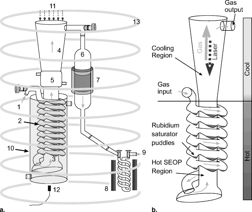
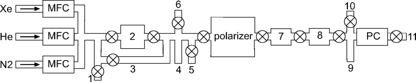
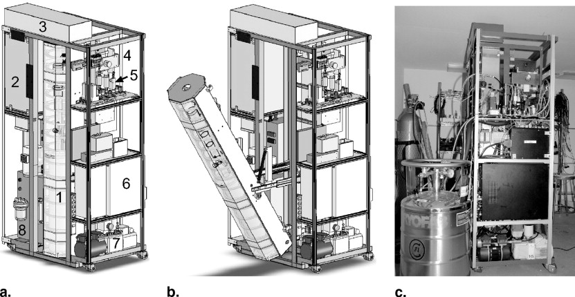
The polarizer is a continuous-flow system capable of producing large quantities of highly-polarized 129 Xe through rubidium spin-exchange optical pumping. The low-pressure, high-velocity operating regime takes advantage of the enhancement in the spin exchange rate provided by van der Waals molecules dominating the atomic interactions. The long polarizing column moves the flow of the gas opposite to the laser direction, allowing efficient extraction of the laser light. Separate sections of the system assure full rubidium vapor saturation and removal.
Results
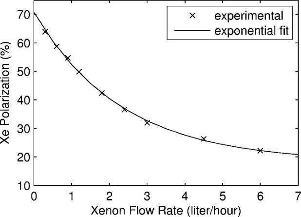
The system is capable of producing 64% polarization at 0.3 L/hour Xe production rate. Increasing xenon flow reduces output polarization. Xenon polarization was studied as a function of different system operating parameters. A novel xenon trapping design was demonstrated to allow full recovery of the xenon polarization after the freeze-thaw cycle. Delivery methods of the gas to an offsite MRI facility were demonstrated in both frozen and gas states.
Conclusions
We demonstrated a new concept for producing large quantities of highly polarized xenon. The system is operating in an MRI facility producing liters of hyperpolarized gas for human lung imaging studies.
Although protons in living tissue achieve sufficient thermal polarization for standard magnetic resonance imaging (MRI) procedures, gaseous samples have three orders of magnitude lower density, making diagnostic imaging impractical. Similarly, the low body tissue density and susceptibility mismatched interfaces inside the lungs present a challenge to proton MRI of the lungs. Hyperpolarized gases are polarized by alternative methods, such as spin-exchange optical pumping (SEOP) ( ) or metastability exchange optical pumping ( ), to extremely high values to compensate for the density difference, and they offer great potential as imaging agents. They can be introduced into the body noninvasively by breathing and imaged with no background. Two noble gases, 3 He and 129 Xe, have nuclear spin half and gyromagnetic ratios relative to that of the proton of 0.76 and 0.28, respectively. They present the advantage of having zero quadrupole moment and, as a consequence, long T 1 relaxation times after being polarized. Although the first MRI application of hyperpolarized noble gases involved 129 Xe ( ), thereafter the research community focused mainly on 3 He because of the well-established polarizing methods ( ). Relatively large quantities of hyperpolarized 3 He are produced with 50%–80% polarization using metastability-exchange optical pumping. 3 He in the gas state has a T 1 relaxation time that can reach days and even weeks ( ). As a beneficial consequence, 3 He can be distributed from a central polarizing site to MRI centers ( ). Practical limitations of MRI studies involving 3 He include its confinement to the lung gas space only ( ), because its solubility in blood and tissue is extremely low ( ). Also, its unnatural source on Earth, mainly coming from tritium radioactive decay, makes its future widespread clinical applicability questionable. In contrast, xenon is extracted from the atmosphere by partial distillation, with the desired 129 Xe isotope having significant 26.4% natural abundance. Commercial enrichment can raise that abundance by a factor of three or more. Xenon is soluble in blood with a large partition coefficient of ∼0.1 ( ) and readily diffuses throughout tissues. 129 Xe displays a nuclear magnetic resonance (NMR) spectrum with chemical shifts in resonance frequency that characterize its microscopic/molecular environment ( ). It offers longitudinal magnetization that survives several seconds to several tens of seconds in vivo ( ). The time and spatial dependence of its distribution in the body can reveal functional attributes ( ). Xenon biologic effects of anesthesia are well characterized and well tolerated ( ).
Spin-exchange optical pumping ( ) relies on the unpaired electron of the alkali atoms, such as Rb, which is polarized through resonant interaction with circularly polarized light provided by a continuous laser source. Subsequently, the polarization is transferred through a Fermi-contact dipole-dipole interaction to the noble gas nucleus. The presence of nitrogen is required in the gas mixture for quenching the fluorescence of the excited alkali vapor atoms ( ). Natural helium ( 4 He) is also commonly used as a buffer gas to increase the overall pressure inside the cell in order to take advantage of the pressure broadening effects on the Rb D1 absorption line ( ).
Get Radiology Tree app to read full this article<
Get Radiology Tree app to read full this article<
Get Radiology Tree app to read full this article<
PXe=PAγSEγSE+Γ[1−e−t(γSE+Γ)] P
Xe
=
P
A
γ
SE
γ
SE
+
Γ
[
1
−
e
−
t
(
γ
SE
+
Γ
)
]
where P A is the alkali vapor polarization, Γ is the noble gas nuclear spin-destruction rate, and γ SE is the spin-exchange rate between the alkali atoms and gas nuclei. Similar to the alkali, the noble gas nuclei can lose their polarization interacting with the container walls or with the other atoms in the composition. Xenon polarization can never exceed the rubidium polarization. Moreover, to approach the Rb polarization, the noble gas has to be in contact with the alkali vapor for several spin-up e-folding times. The spin-up time is defined as (γ SE + Γ) –1 , and for Rb-Xe pairs under our operating conditions is on the order of seconds. This implies that high polarizations of xenon can be achieved only if low concentrations of xenon are in contact with highly polarized rubidium for characteristically long times: the challenge of producing large quantities of highly polarized xenon.
Get Radiology Tree app to read full this article<
Materials and methods
Get Radiology Tree app to read full this article<
Get Radiology Tree app to read full this article<
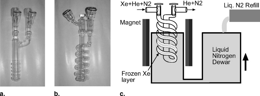
Polarizing Column
Get Radiology Tree app to read full this article<
B 0 Field
Get Radiology Tree app to read full this article<
Gas Flow System
Get Radiology Tree app to read full this article<
Get Radiology Tree app to read full this article<
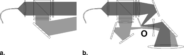
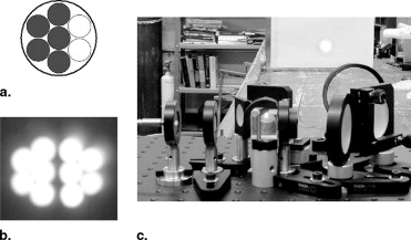
Laser and Optics
Get Radiology Tree app to read full this article<
Get Radiology Tree app to read full this article<
Heating Oven
Get Radiology Tree app to read full this article<
Xenon Accumulation System
Get Radiology Tree app to read full this article<
Get Radiology Tree app to read full this article<
Polarization Measurement
Get Radiology Tree app to read full this article<
Get Radiology Tree app to read full this article<
SXeSp=PXePpNXeβ129Npsin(αXe)sin(αp)γXeγpe−tdisc/T∗2,Xee−tdisc/T∗2,p S
Xe
S
p
=
P
Xe
P
p
N
Xe
β
129
N
p
sin
(
α
Xe
)
sin
(
α
p
)
γ
Xe
γ
p
e
−
t
d
i
s
c
/
T
2
,
X
e
*
e
−
t
d
i
s
c
/
T
2
,
p
*
where S is the free induction decay amplitude (or the integral of the fast Fourier transform of the signal), N is the number of nuclei in the measured volume, β 129 is the isotopic abundance of the 129 Xe, α is the excitation flip angle, and γ is the nuclear gyromagnetic ratio. The last correction factor in Eq 2 is to account for T∗2 T
2
* losses during the delay time before the start of acquisition, necessary because of coil coupling. It extrapolates the signal value back to time t aq = 0 and it is significant because of different T∗2 T
2
* values between proton and xenon. For protons, the polarization is given by the Boltzmann equilibrium of the spins inside the low magnetic field needed to observe a 33.7 kHz NMR frequency of 7.92 gauss ( P = 2.6 × 10 –9 at room temperature). To obtain a good SNR for the proton signal, long acquisition times are required (usually 1,024 averages with a 15-second repetition time between the shots). The number of xenon atoms was calculated based on the ideal gas law. Xenon files are acquired using four averages with 90° flip angle. The repetition time is chosen such that the gas inside the down-tube NMR region, depleted of its magnetization by the measurement, is completely replaced by polarized gas mixture (typically 20 seconds).
Get Radiology Tree app to read full this article<
Transportation System
Get Radiology Tree app to read full this article<
Get Radiology Tree app to read full this article<
Results
Get Radiology Tree app to read full this article<
Get Radiology Tree app to read full this article<
Xenon Polarization
Get Radiology Tree app to read full this article<
Freeze-Thaw Polarization Recovery
Get Radiology Tree app to read full this article<
Gas Phase Relaxation Measurements
Get Radiology Tree app to read full this article<
Production Rates
Get Radiology Tree app to read full this article<
P=P0(1−e−tacc/T1)T1tacc P
=
P
0
(
1
−
e
−
t
a
c
c
/
T
1
)
T
1
t
a
c
c
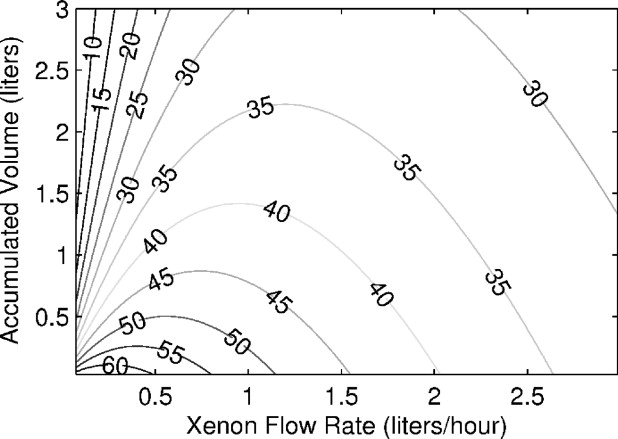
where T 1 is the longitudinal relaxation time in frozen state and t acc is the accumulation time. If the output gas polarization can be estimated as a function of its flow rate, P 0 = P 0 (Φ), then one can calculate the optimum xenon flow rate and the required time to be produced. We fitted the experimental data shown in Fig 7 with an exponential function resulting in:
P0(Φ)=18.25+52.51×e−Φ(sih)2.32(%) P
0
(
Φ
)
=
18.25
+
52.51
×
e
−
Φ
(
sih
)
2.32
(
%
)
Figure 8 shows the xenon production map generated by implementing Eq 4 into Eq 3 . The displayed polarization numbers do not include any losses from the freeze-thaw cycle and they are characteristic for 2.5 hours of xenon relaxation time in a frozen state. The map shows that our system can produce a half-liter of xenon with polarization ∼50% or 1 L of xenon with polarization ∼44%.
Get Radiology Tree app to read full this article<
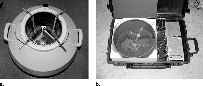
Polarizer Relocation
Get Radiology Tree app to read full this article<
Compact Prototype System
Get Radiology Tree app to read full this article<
Get Radiology Tree app to read full this article<
Discussion
Get Radiology Tree app to read full this article<
Get Radiology Tree app to read full this article<
References
1. Bouchiat M.R., Carver T.R., Varnum C.M.: Nuclear polarization in He 3 gas induced by optical pumping in dipolar exchange. Phys Rev Lett 1960; 5: pp. 373-375.
2. Colegrove F.D., Schearer L.D., Walters G.K.: Polarization of he 3 gas by optical pumping. Phys Rev 1963; 132: pp. 2561-2572.
3. Albert M.S., Cates G.D., Driehuys B., et. al.: Biological magnetic resonance imaging using laser-polarized 129 Xe. Nature (London) 1994; 370: pp. 199-201.
4. Wagshul M.E., Chupp T.E.: Laser optical pumping of high-density Rb in polarized 3he targets. Phys Rev A 1994; 49: pp. 3854-3869.
5. Eckert G., Heil W., Meyerhoff M., et. al.: A dense polarized 3 He target based on compression of optically pumped gas. Nucl Instrum Methods Phys Res A 1992; 320: pp. 53-65.
6. Rich D.R., Gentile T.R., Smith T.B., et. al.: Spin exchange optical pumping at pressures near 1 bar for neutron spin filters. Appl Phys Lett 2002; 80: pp. 2210-2212.
7. Deninger A., Heil W., Wolf M., et. al.: Paramagnetic relaxation of spin polarized 3 He at coated glass walls. Eur Phys J D 2006; 38: pp. 439-443.
8. van Beek E.J.R., Schmiedeskamp J., Wild J.M., et. al.: Hyperpolarized 3-helium MR imaging of the lungs: testing the concept of a central production facility. Eur Radiol 2003; 13: pp. 2583-2586.
9. Gast K.K., Eberle B., Schmiedeskamp J., et. al.: Magnetic resonance imaging using hyperpolarized 3He-Gas. Acad Radiol 2003; 10: pp. 1119-1131.
10. Fischer M.C., Kadlecek S., Yu J., et. al.: Measurements of regional alveolar oxygen pressure using hyperpolarized 3He MRI. Acad Radiol 2005; 12: pp. 1430-1439.
11. Conradi M.S., Yablonskiy D.A., Woods J.C., et. al.: 3He diffusion MRI of the lung. Acad Radiol 2005; 12: pp. 1406-1413.
12. Albert M.S., Balamore D.: Development of hyperpolarized noble gas MRI. Nucl Instrum Methods Phys Res A 1998; 402: pp. 441-453.
13. Goto T., Suwa K., Uezono S., et. al.: The blood-gas partition coefficient of xenon may be lower than generally accepted. Br J Anaesth 1998; 80: pp. 255-256.
14. Raftery D., Long H., Meersmann T., et. al.: High-field NMR of adsorbed xenon polarized by laser pumping. Phys Rev Lett 1991; 66: pp. 584-587.
15. Pietraiss T., Gaede H.C.: Optically polarized 129 Xe in NMR spectroscopy. Adv Mat 1995; 7: pp. 826-838.
16. Wagshul M.E., Button T.M., Haifang F.L., et. al.: In vivo MR imaging and spectroscopy using hyperpolarized 129xe. Magn Reson Med 1996; 36: pp. 183-191.
17. Bifone A., Song Y.Q., Seydoux R., et. al.: NMR of laser-polarized xenon in human blood. Proc Natl Acad Sci U S A 1996; 93: pp. 12932-12936.
18. Butler J.P., Mair R.W., Hoffmann D., et. al.: Measuring surface-area-to-volume ratios in soft porous materials using laser-polarized xenon interphase exchange nuclear magnetic resonance. J Phys Condens Matter 2002; 14: pp. L297-L304.
19. Ruppert K., Mata J.F., Brookeman J.R., et. al.: Exploring lung function with hyperpolarized (129)Xe nuclear magnetic resonance. Magn Reson Med 2004; 51: pp. 676-687.
20. Sanders R.D., Ma D., Maze M.: Xenon: elemental anaesthesia in clinical practice. Br Med Bull 2004; 71: pp. 115-135.
21. Happer W.: Optical pumping. Rev Mod Phys 1972; 44: pp. 169-250.
22. Romalis M.V., Miron E., Cates G.D.: Pressure broadening of RB D1 and D2 lines by 3He, 4He, N2, and XE: line cores and near wings. Phys Rev A 1997; 56: pp. 4569-4578.
23. Ruth U., Hof T., Schmidth J., et. al.: Production of nitrogen-free, hyperpolarized 129 Xe gas. Appl Phys B 1999; 68: pp. 93-97.
24. Chann B., Babcock E., Anderson L.W., et. al.: Skew light propagation in optically thick optical pumping cells. Phys Rev A 2002; 66: pp. 033406.
25. Kuzma N.N., Patton N., Raman K., et. al.: Fast nuclear spin relaxation in hyperpolarized solid 129-xenon. Phys Rev Lett 2002; 88: pp. 147602.
26. Ruset I.C., Ketel S., Hersman F.W.: Optical pumping system design for large production of hyperpolarized 129xe. Phys Rev Lett 2006; 96: pp. 053002.
27. Patton B., Kuzma N.N., Happer W.: Reducing the relaxation of frozen hyperpolarized 129xe during cryogenic separation. Proc 35th DAMOP 2004; C4.011
28. Patz S., Hersman F.W., Muradian I., et. al.: Hyperpolarized 129 Xe MRI: A viable functional lung imaging modality?. Eur J Radiol 2007; In press
29. Zhu H., Ruset I.C., Hersman F.W.: Spectrally narrowed external-cavity high-power stack of laser diode arrays. Opt Lett 2005; 30: pp. 1342-1344.