
Rationale and Objective
To identify the influence of various parameters for reducing artifacts in computed tomography (CT) of commonly used pacemakers or implantable cardioverter-defibrillator (ICD) lead tips.
Materials and Methods
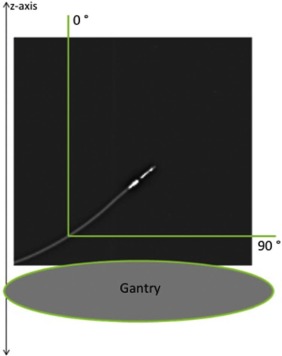
This ex vivo phantom study compared two CT techniques (Dual-Energy CT [DECT] vs. Dual-Source CT [DSCT]), as well as the influence of incremental alterations of current-time product and pacemaker lead-tip angle with respect to the gantry plane. Four pacemaker leads and one ICD lead were evaluated. The images were assessed visually on a five-point Likert scale (1 = artifact free to 5 = massive artifacts). Likert values 1–3 represent clinically relevant, diagnostic image quality.
Results
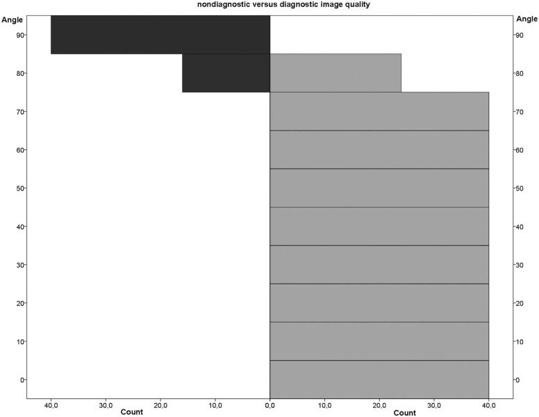
344 of 400 total images were rated with diagnostic image quality. The DECT and dual-source DSCT technique each scored 86% diagnostic image quality. Statistically, DECT images showed significantly improved image quality ( P < .05). Concerning the current-time product, no statistically significant change was found. Regarding lead-tip positioning, an angle of ≤70° yielded 100% diagnostic image quality. Pacemaker and ICD leads were assessed to have statistically significant differences.
Conclusions
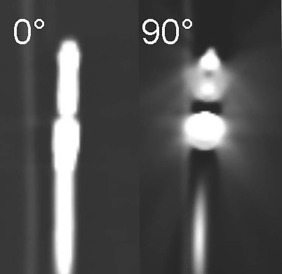
Surprisingly, the lead-tip angle of 70° has been established as the key angle under which diagnostic image quality is always ensured, regardless of the imaging technique. Thus, we call 70° the “Magic angle” in CT pacemaker imaging.
Introduction
Patients with implanted metallic devices are a common sight in clinical practice using computed tomography (CT). In particular, more than one million cardiovascular implantable electronic devices such as pacemakers (PMs) and implantable cardioverter-defibrillators (ICDs) are being implanted in patients with cardiovascular diseases every year, and this number is rising .
These devices are usually implanted in an infraclavicular subcutaneous or submuscular pocket with a transvenous lead. Most ventricular leads are placed in the apex of the right ventricle (RV), and most atrial leads are implanted in the right atrial appendage. There is a 4.4% incidence of a lead dislodgement or malfunctioning (~44,000 patients) 1 year after implantation from which approximately 10,000 patients are suffering from possible lead perforation.
Get Radiology Tree app to read full this article<
Get Radiology Tree app to read full this article<
Get Radiology Tree app to read full this article<
Materials and Methods
CT Data Acquisition and Experimental Setup
Get Radiology Tree app to read full this article<
Get Radiology Tree app to read full this article<
Get Radiology Tree app to read full this article<
Image Post-Processing or Evaluation
Get Radiology Tree app to read full this article<
Get Radiology Tree app to read full this article<
Get Radiology Tree app to read full this article<
Get Radiology Tree app to read full this article<
Get Radiology Tree app to read full this article<
Statistics
Get Radiology Tree app to read full this article<
Result
Get Radiology Tree app to read full this article<
Get Radiology Tree app to read full this article<
Technique or Protocol
Evaluation DECT versus DSCT
Get Radiology Tree app to read full this article<
TABLE 1
Mean Likert Values ± Standard Deviation of Each Pacemaker Lead Are Shown with Regard to the Specific CT Technique Setting.
Pacemaker 1 Pacemaker 2 † Pacemaker 3 Pacemaker 4 ICD ‡ Boston Scientific CapSure SP Novus 4592 CapSure Sense 4074 CapSureFix Novus 5076 St Jude Medical DECT 1 \* (65 mAs) 2.2 ± 1.4 2.0 ± 1.2 2.0 ± 1.0 2.4 ± 0.8 2.3 ± 1.3 2.2 ± 1.1 (for DECT) DECT 2 \* (125 mAs) 2.2 ± 1.4 2.0 ± 1.2 2.1 ± 1.0 2.3 ± 0.9 2.3 ± 1.3 DECT 3 \* (185 mAs) 2.2 ± 1.4 2.0 ± 1.2 2.3 ± 1.0 2.3 ± 0.9 2.3 ± 1.3 DSCT 1 (150 mAs) 2.3 ± 1.3 2.0 ± 1.2 2.3 ± 1.0 2.4 ± 0.8 2.6 ± 1.0 2.3 ± 1.0 (for DSCT) DSCT 2 (200 mAs) 2.3 ± 1.3 2.0 ± 1.2 2.3 ± 1.0 2.4 ± 0.8 2.6 ± 1.0 DSCT 3 (250 mAs) 2.3 ± 1.3 2.0 ± 1.2 2.3 ± 1.0 2.4 ± 0.8 2.6 ± 1.0 DSCT 4 (300 mAs) 2.3 ± 1.3 2.0 ± 1.2 2.3 ± 1.0 2.4 ± 0.8 2.7 ± 0.8 DSCT 5 (370 mAs) 2.3 ± 1.3 2.0 ± 1.2 2.3 ± 1.0 2.4 ± 0.8 2.7 ± 0.8 2.26 ± 1.3 2.00 ± 1.1 2.21 ± 0.9 2.37 ± 0.8 2.51 ± 1.0
No significant differences are evident between protocols of the same technique (eg, DSCT 1 vs. DSCT 2) (significance level: P < .05).
Get Radiology Tree app to read full this article<
Get Radiology Tree app to read full this article<
Get Radiology Tree app to read full this article<
Get Radiology Tree app to read full this article<
Evaluation of Increasing Increments of Current-Time Product
Get Radiology Tree app to read full this article<
Evaluation Regarding Lead-tip Angle
Get Radiology Tree app to read full this article<
Get Radiology Tree app to read full this article<
Evaluation with Regard to Lead Design: Pacemaker versus ICD
Get Radiology Tree app to read full this article<
Get Radiology Tree app to read full this article<
Get Radiology Tree app to read full this article<
Get Radiology Tree app to read full this article<
Observer
Get Radiology Tree app to read full this article<
Get Radiology Tree app to read full this article<
Discussion
Get Radiology Tree app to read full this article<
Technique
Get Radiology Tree app to read full this article<
Get Radiology Tree app to read full this article<
Get Radiology Tree app to read full this article<
Get Radiology Tree app to read full this article<
Get Radiology Tree app to read full this article<
Get Radiology Tree app to read full this article<
Angle
Get Radiology Tree app to read full this article<
Get Radiology Tree app to read full this article<
Get Radiology Tree app to read full this article<
Get Radiology Tree app to read full this article<
Get Radiology Tree app to read full this article<
Get Radiology Tree app to read full this article<
Pacemaker
Get Radiology Tree app to read full this article<
Observer
Get Radiology Tree app to read full this article<
Limitations
Get Radiology Tree app to read full this article<
Get Radiology Tree app to read full this article<
Get Radiology Tree app to read full this article<
Get Radiology Tree app to read full this article<
Get Radiology Tree app to read full this article<
Get Radiology Tree app to read full this article<
Conclusion
Get Radiology Tree app to read full this article<
Get Radiology Tree app to read full this article<
Get Radiology Tree app to read full this article<
Get Radiology Tree app to read full this article<
Acknowledgments
Get Radiology Tree app to read full this article<
Get Radiology Tree app to read full this article<
Get Radiology Tree app to read full this article<
References
1. Mond H.G., Proclemer A.: The 11th world survey of cardiac pacing and implantable cardioverter-defibrillators: calendar year 2009—a World Society of Arrhythmia’s project. Pacing Clin Electrophysiol 2011; 34: pp. 1013-1027.
2. Ghani A., Delnoy P.P., Ramdat Misier A.R., et. al.: Incidence of lead dislodgement, malfunction and perforation during the first year following device implantation. Neth Heart J 2014; 22: pp. 286-291.
3. Achenbach S., Barkhausen J., Beer M., et. al.: Konsensusempfehlungen der DRG / DGK / DGPK zum Einsatz der Herzbildgebung mit Computertomographie und Magnetresonanztomographie. Der Kardiologe 2012; 2: pp. 105-125.
4. Lell M., Marwan M., Schepis T., et. al.: Prospectively ECG-triggered high-pitch spiral acquisition for coronary CT angiography using dual source CT: technique and initial experience. Eur Radiol 2009; 19: pp. 2576-2583.
5. Guggenberger R., Winklhofer S., Osterhoff G., et. al.: Metallic artefact reduction with monoenergetic dual-energy CT: systematic ex vivo evaluation of posterior spinal fusion implants from various vendors and different spine levels. Eur Radiol 2012; 22: pp. 2357-2364.
6. Srinivasan A., Hoeffner E., Ibrahim M., et. al.: Utility of dual-energy CT virtual keV monochromatic series for the assessment of spinal transpedicular hardware-bone interface. AJR Am J Roentgenol 2013; 201: pp. 878-883.
7. Yu L., Leng S., McCollough C.H.: Dual-energy CT–based monochromatic imaging. AJR Am J Roentgenol 2012; 199: pp. S9-S15.
8. Kuchenbecker S., Faby S., Sawall S., et. al.: Dual energy CT: how well can pseudo-monochromatic imaging reduce metal artifacts?. Med Phys 2015; 42: pp. 1023-1036.
9. Takrouri H.S., Alnassar M.M., Amirabadi A., et. al.: Metal artifact reduction: added value of rapid-kilovoltage-switching dual-energy CT in relation to single-energy CT in a piglet animal model. AJR Am J Roentgenol 2015; 205: pp. W352-W359.
10. Bamberg F., Dierks A., Nikolaou K., et. al.: Metal artifact reduction by dual energy computed tomography using monoenergetic extrapolation. Eur Radiol 2011; 21: pp. 1424-1429.
11. Filograna L., Magarelli N., Leone A., et. al.: Value of monoenergetic dual-energy CT (DECT) for artefact reduction from metallic orthopedic implants in post-mortem studies. Skeletal Radiol 2015; 44: pp. 1287-1294.
12. Pessis E., Campagna R., Sverzut J.-M., et. al.: Virtual monochromatic spectral imaging with fast kilovoltage switching: reduction of metal artifacts at CT. Radiographics 2013; 33: pp. 573-583.
13. Roth T.D., Maertz N.A., Parr J.A., et. al.: CT of the hip prosthesis: appearance of components, fixation, and complications. Radiographics 2012; 32: pp. 1089-1107.
14. Boas F.E., Fleischmann D.: Evaluation of two iterative techniques for reducing metal artifacts in computed tomography. Radiology 2011; 259:
15. Lee M.-J., Kim S., Lee S.-A., et. al.: Overcoming artifacts from metallic orthopedic implants at high-field-strength MR imaging and multidetector CT. Radiographics 2007; 27: pp. 791-803.
16. Haramati N., Staron R.B., Mazel-Sperling K., et. al.: CT scans through metal scanning technique versus hardware composition. Comput Med Imaging Graph 1994; 18: pp. 429-434.
17. Barrett J.F., Keat N.: Artifacts in CT: recognition and avoidance. Radiographics 2004; 24: pp. 1679-1691.
18. De Man B., Nuyts J., Dupont P., et. al.: Metal streak artifacts in X-ray computed tomography: simulation study. IEEE Trans Nucl Sci 1999; 46: pp. 691-696.
19. Mori I., Machida Y., Osanai M., et. al.: Photon starvation artifacts of X-ray CT: their true cause and a solution. Radiol Phys Technol 2013; 6: pp. 130-141.