
Rationale and Objectives
To compare the effectiveness of multiacquisition with variable resonance image combination selective (MAVRIC SL) with conventional two-dimensional fast spin-echo (2D-FSE) magnetic resonance (MR) techniques at 3T in imaging patients with a variety of metallic implants.
Materials and Methods
Twenty-one 3T MR studies were obtained in 19 patients with different types of metal implants. Paired MAVRIC SL and 2D-FSE sequences were reviewed by two radiologists and compared for in-plane and through-plane metal artifact, visualization of the bone implant interface and surrounding soft tissues, blurring, and overall image quality using a two-tailed Wilcoxon signed rank test. The area of artifact on paired images was measured and compared using a paired Wilcoxon signed rank test. Changes in patient management resulting from MAVRIC SL imaging were documented.
Results
Significantly less in-plane and through-plane artifact was seen with MAVRIC SL, with improved visualization of the bone–implant interface and surrounding soft tissues, and superior overall image quality ( P = .0001). Increased blurring was seen with MAVRIC SL ( P = .0016). MAVRIC SL significantly decreased the image artifact compared to 2D-FSE ( P = .0001). Inclusion of MAVRIC SL to the imaging protocol determined the need for surgery or type of surgery in five patients and ruled out the need for surgery in 13 patients. In three patients, the area of interest was well seen on both MAVRIC SL and 2D-FSE images, so the addition of MAVRIC had no effect on patient management.
Conclusions
Imaging around metal implants with MAVRIC SL at 3T significantly improved image quality and decreased image artifact compared to conventional 2D-FSE imaging techniques and directly impacted patient management.
Metallic orthopedic implants are now commonplace in modern joint and spine surgery. However, subsequent magnetic resonance (MR) imaging of symptomatic patients with orthopedic hardware is often limited by metallic susceptibility artifacts, resulting in signal loss, pileup artifact, and geometric distortion . Two MR imaging methods have recently been introduced that significantly reduce susceptibility artifact near metal implants: slice encoding for metal artifact correction (SEMAC) and multiacquisition variable resonance image combination (MAVRIC) . Both techniques use multiple excitations to excite the overall volume being imaged, but SEMAC excites standard slices (limited spatial bands), whereas MAVRIC excites limited frequency bands. As the extent of susceptibility, artifact is directly proportional to field strength; these metal suppression sequences are typically applied at field strengths no higher than 1.5 Tesla (1.5T) . However, the increasing use of 3 Tesla (3T) scanners makes it important to develop and evaluate metal suppression techniques at higher field strengths.
The SEMAC technique uses additional phase encoding in the slice direction to correct for through-plane distortion, combined with view-angle tilting (VAT) and a spin-echo acquisition to avoid in-plane distortion and T2* signal loss. The three-dimensional (3D) spin-echo acquisition is used to resolve the profile of each excited slice in the region of interest. MAVRIC excites a series of limited spectral bandwidths and uses the same 3D spin-echo readout to resolve distortion, exploiting the limited excited frequency range to avoid in-plane distortion. Overall, MAVRIC’s spectral overlap strategy to smoothly combine separately encoded spectral bins tends to yield composite images that have higher signal-to-noise ratios (SNR) than images constructed with SEMAC’s nonoverlapping slices . Unfortunately, in cases where surface coils fail to provide adequate volume selectivity around large joints, such as the hip and shoulder, MAVRIC’s lack of z -selectivity can result in significant through-plane aliasing.
Get Radiology Tree app to read full this article<
 Open full size image
Figure 1
Pulse sequence diagram for multiacquisition with variable resonance image combination selective (MAVRIC SL), where RF is radiofrequency, G z is the slice-select gradient, G y is the phase-encoding gradient and G x is the frequency-encoding gradient. The MAVRIC SL sequence is based on a standard spin-echo train imaging sequence (such as three-dimensional fast spin-echo, Cube, Space, VISTA). The excitation and refocusing RF pulses are Gaussian shaped, with overlap between adjacent excited regions, which are typically about 8- to 12-mm thick. Typically, a reduced refocusing flip angle (135° or 120°) is used instead of 180°, to reduce specific absorption rate. Phase encoding in both slice and phase directions is used, allowing the sequence to resolve through-slice distortions. A view-angle–tilting gradient is applied on the slice axis during the readout gradient to correct in-plane distortions.
Get Radiology Tree app to read full this article<
Get Radiology Tree app to read full this article<
Materials and methods
Subjects
Get Radiology Tree app to read full this article<
Image Acquisition
Get Radiology Tree app to read full this article<
Get Radiology Tree app to read full this article<
Image Analysis
Get Radiology Tree app to read full this article<
Qualitative Analysis
Get Radiology Tree app to read full this article<
Quantitative Analysis
Get Radiology Tree app to read full this article<
Get Radiology Tree app to read full this article<
Clinical History
Get Radiology Tree app to read full this article<
Statistical Analysis
Get Radiology Tree app to read full this article<
Get Radiology Tree app to read full this article<
Get Radiology Tree app to read full this article<
Results
Qualitative Analysis
Get Radiology Tree app to read full this article<
Table 1
Comparison of Image Quality Between MAVRIC SL and 2D-FSE images
Study Characteristics Mean Grades for Readers 1 and 2 Study# Structure Imaged Plane MAVRIC SL Image Contrast 2D-FSE Image Contrast Extent of In-Plane Metal Artifact Extent of Through-Plane Metal Artifact Visualization of Bone–Implant Interface Visualization of Surrounding Soft Tissues Image Blurring Overall Image Quality 1 Spine Sagittal PD T2 −2 −2 −1 −2 1 −1 2 Spine Axial PD T2 −2 −2 −2 −2 1 −2 3 Hip Axial PD T2 IDEAL −2 −2 −2 −2 1 −2 4 Hip Coronal PD T1 −2 −2 −2 −2 0 −2 5 Hip Axial IR T1 −2 −2 −2 −2 1 −1 6 Hip Axial PD T2 IDEAL −2 −2 −2 −2 0 −2 7 Hip Axial PD T2 IDEAL −2 −2 −2 −2 0 −1.5 8 Hip Coronal PD PD −2 −2 −2 −2 1 −2 9 Hip Coronal PD PD −2 −2 −2 −2 0 −2 10 Hip Coronal PD T1 −2 −2 −2 −2 0 −2 11 Hip Coronal IR T1 −2 −1 −2 0 1 −1 12 Hip Axial IR T1 −2 −2 −2 −2 2 −2 13 Hip Axial PD T1 −2 −2 −2 −2 2 −2 14 Hip Coronal PD T1 −2 −2 −2 −2 0 −2 15 Hip Coronal PD PD −2 −2 −2 −2 1 −2 16 Knee Sagittal PD PD −2 −1 −2 −2 1 −2 17 Knee Axial IR T1 −2 −2 −2 −2 0 −2 18 Knee Coronal PD T1 −2 −2 −2 −2 1 −2 19 Knee Sagittal PD PD −2 −2 −2 −1 0 −2 20 Knee Coronal IR T1 −2 −2 −2 −2 1 −2 21 Foot Sagittal IR T1 −2 −2 −2 −2 1 −2 Mean grade for all patients −2 1.9 −1.95 −1.86 0.71 −1.83
2D-FSE, two-dimensional fast spin-echo; IDEAL, iterative decomposition of water and fat with echo asymmetry and least-squares estimation; IR, inversion recovery; MAVRIC SL, multiacquisition with variable resonance image combination slice selective; PD, proton density.
Grading scale: −2 = MAVRIC SL much better than 2D-FSE; −1 = MAVRIC SL somewhat better than 2D-FSE; 0 = no difference between images; +1 = 2D-FSE somewhat better than MAVRIC SL; and +2 = 2D-FSE much better than MAVRIC SL.
Get Radiology Tree app to read full this article<
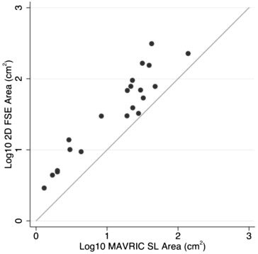
Quantitative Analysis
Get Radiology Tree app to read full this article<
Clinical History
Get Radiology Tree app to read full this article<
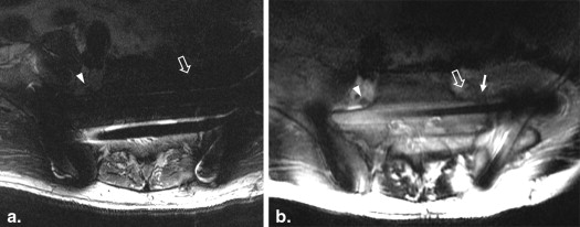
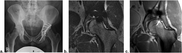
Table 2
Imaging Findings Seen Only on MAVRIC SL That Either Resulted in Surgical Intervention or Determined What Type of Surgery Was Necessary
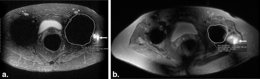
Presenting Symptom Imaging Findings on MAVRIC SL Surgical Findings and Intervention Outcome 63-year-old man with acute onset of foot drop after open reduction and internal fixation of complex pelvic and sacral fractures Impingement of L5 nerve root over the fracture site L5 nerve root tethered and compressed along the superior aspect of the sacrum at the site of fracture. Nerve decompressed and dissected free from scar tissue, with resection of superior margin of anterior sacrum Significant improvement in pain at 2-week follow-up but persistent foot drop. Foot drop persists at 2-year follow-up 74-year-old woman with recurrent hip pain after total hip replacement Complete tear of the gluteus medius and minimus tendons Extensive tear of gluteus medius and minimus tendons, with severe fibrofatty atrophy of the gluteus minimus muscle. Abductor tendon reconstruction rerouting the tensor fascia lata through the greater trochanter Markedly improved abductor strength at 2-week follow up (>4/5 muscle strength). Continued to do well at 6-month follow-up 57-year-old woman with a total hip replacement and two prior dislocations of the prosthetic hip. Presenting with hip stiffness and weakness, primarily of abductor strength. Radiographs demonstrated a steep acetabular cup, with evidence of polyethylene wear but no obvious periprosthetic osteolysis. Hip joint effusion but no evidence of particle disease. Intact gluteal tendons but marked atrophy and fatty infiltration of the gluteal muscles. Acetabular component replaced for abnormal cup position and marked polyethylene wear, with no need for revision of femoral component or gluteal tendon reconstruction. No further instability of hip at 1-year follow-up after intense physical therapy. 22-year-old synchronized swimmer with hip pain 6 months after placement of three percutaneous screws for femoral neck stress fracture Absence of osteonecrosis in the femoral head Removal of symptomatic hardware, stress fracture well healed Asymptomatic at 2-week follow-up and returned to swimming for the season. No further issues at 6-month follow-u 38-year-old man with prior plate and screw fixation of a left acetabular fracture with continued hip pain Tear of the anterosuperior acetabular labrum, with bony prominence of femoral head–neck junction Acetabular labrum torn from acetabular margin from 11- to 1-o’clock position, with large chondral flap. Underwent labral repair, chondral debridement, and microfracture, plus osteochondroplasty of femoral head–neck junction Residual pain and clicking at 3-month follow-up but significant improvement at 4-month follow-up. However, 2-year follow-up showed progression of osteoarthritis and is being considered for hip arthroplasty
MAVRIC SL, multiacquisition with variable resonance image combination slice selective.
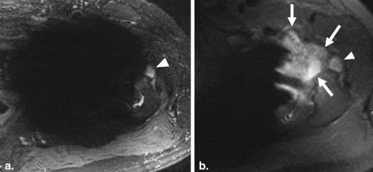
Table 3
Imaging Findings on MAVRIC SL Resulting in a Decision Not to Operate
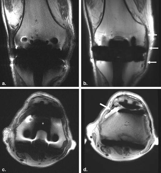
Subject Population Imaging Findings Subsequent Management Outcome 73-year-old man with painful back years after spinal fusion with transfacet screws and iliac crest bone graft Postoperative changes, with no significant neural compressive lesion Physical therapy and trigger point injections for hypertonic muscles Interval improvement at 5-week follow-up 57-year-old woman with hip pain, status-post total hip replacement (THR) Partial-thickness gluteus medius tendon tear Physical therapy Interval improvement at 4-month follow-up 64-year-old man with hip pain, status-post THR Large hip joint effusion Physical therapy No follow-up recorded in patient’s medical records 55-year-old woman with hip pain, status-post THR Pseudotumor ruled out Physical therapy No improvement—felt to be overloading THR because of severe osteoarthritis in contralateral hip, which was subsequently replaced with excellent clinical outcome in both hips 45-year-old man with hip pain, status-post THR Pseudotumor ruled out Bone scan, hip aspiration, and steroid injection in iliopsoas tendon sheath Negative bone scan and hip aspirate. No improvement after steroid injection. No additional follow-up recorded. 65-year-old man with metastatic chondrosarcoma and hip pain, status-post THR for ununited femoral fracture in irradiated femur No tumor recurrence Steroid injection Excellent result at 5-month follow-up 27-year-old man with hip pain, status-post placement of bilateral femoral neck screws for slipped capital femoral epiphyses (two studies, one patient) Degenerative change Bilateral steroid injection No significant relief and was subsequently referred to spine clinic 52-year-old man status-post chondrosarcoma resection, with extensive reconstruction of proximal femur No definite tumor recurrence Physical therapy Fractured femoral plate 3 months later and treated surgically 86-year-old man with bilateral knee pain, status-post total knee arthroplasties (two studies, one patient) No significant pathology identified Physical therapy No follow-up recorded in patient’s medical records 47-year-old woman with knee pain status-post total knee arthroplasty, with instability on flexion No significant pathology identified Physical therapy 3-month course of physical therapy, but knee remained unstable and was subsequently revised with liner exchange. Excellent result at follow-up 18-year-old man with painful foot, status-post open reduction and internal fixation of prior navicular stress fracture Healed stress fracture Physical therapy, with taping and icing for 2 weeks No pain at 6-month follow-up
MAVRIC SL, multiacquisition with variable resonance image combination slice selective.
Get Radiology Tree app to read full this article<
Discussion
Get Radiology Tree app to read full this article<
Get Radiology Tree app to read full this article<
Get Radiology Tree app to read full this article<
Get Radiology Tree app to read full this article<
Get Radiology Tree app to read full this article<
Get Radiology Tree app to read full this article<
Get Radiology Tree app to read full this article<
Get Radiology Tree app to read full this article<
Acknowledgments
Get Radiology Tree app to read full this article<
Get Radiology Tree app to read full this article<
References
1. Schenck J.F.: The role of magnetic susceptibility in magnetic resonance imaging: MRI magnetic compatibility of the first and second kinds. Med Phys 1996 Jun; 23: pp. 815-850.
2. Hargreaves B.A., Worters P.W., Pauly K.B., et. al.: Metal-induced artifacts in MRI. AJR Am J Roentgenol 2011 Sep; 197: pp. 547-555.
3. Harris C.A., White L.M.: Metal artifact reduction in musculoskeletal magnetic resonance imaging. Orthop Clin North Am 2006 Jul; 37: pp. 349-359.
4. Lu W., Pauly K.B., Gold G.E., et. al.: SEMAC: slice encoding for metal artifact correction in MRI. Magn Reson Med 2009 Jul; 62: pp. 66-76.
5. Hargreaves B.A., Chen W., Lu W., et. al.: Accelerated slice encoding for metal artifact correction. J Magn Reson Imaging 2010 Apr; 31: pp. 987-996.
6. Koch K.M., Lorbiecki J.E., Hinks R.S., et. al.: A multispectral three-dimensional acquisition technique for imaging near metal implants. Magn Reson Med 2009 Feb; 61: pp. 381-390.
7. Hayter C.L., Koff M.F., Shah P., et. al.: MRI after arthroplasty: comparison of MAVRIC and conventional fast spin-echo techniques. Am J Roentgenol 2011 Sep; 197: pp. W405-W411.
8. Chen C.A., Chen W., Goodman S.B., et. al.: New MR imaging methods for metallic implants in the knee: artifact correction and clinical impact. J Magn Reson Imaging 2011 May; 33: pp. 1121-1127.
9. Koff M.F., Shah P., Koch K.M., et. al.: Quantifying image distortion of orthopedic materials in magnetic resonance imaging. J Magn Reson Imaging 2013 Sept; 38: pp. 610-618.
10. Koch K.M., Brau A.C., Chen W., et. al.: Imaging near metal with a MAVRIC-SEMAC hybrid. Magn Reson Med 2011 Jan; 65: pp. 71-82.
11. Landis J.R., Koch G.G.: The measurement of observer agreement for categorical data. Biometrics 1977 Mar; 33: pp. 159-174.
12. Cho Z.H., Kim D.J., Kim Y.K.: Total inhomogeneity correction including chemical shifts and susceptibility by view angle tilting. Med Phys 1988; 15: pp. 7-11.
13. Lee Y., Lim D., Kim E., et. al.: Feasibility of fat-saturated T2-weighted magnetic resonance imaging with slice encoding for metal artifact correction (SEMAC) at 3T. Magnetic Resonance Imaging 2014; 32: pp. 1001-1005.
14. Tao A., Padua A., Goerner F., et. al.: SEMAC-VAT and MSVAT-SPACE sequence strategies for metal; artifact reduction in 1.5T magnetic resonance imaging. Investigative Radiology 2012; 47: pp. 267-276.
15. Li G., Nittka M., Paul D., et. al.: MSVAT-SPACE for fast metal implants imaging.2010.pp. 3171. Proceedings of the 18 th ISMRM Annual Meeting, Stockholm Sweden
16. Irarrazabal P., Nishimura D.G.: Fast three dimensional magnetic resonance imaging. Magn Reson Med 1995 May; 33: pp. 656-662.
17. Koch K.M., King K.F., McKinnon G.C.: B1 effects when imaging near metal implants at 3T.2010.pp. 3082. Proceedings of the 18 th ISMRM Annual Meeting, Stockholm Sweden