
Rationale and Objectives
Modern computed tomographic scanners and examination protocols often require high injection rates of iodinated contrast media (CM). The purpose of this study was to investigate the maximum injection pressures (MIPs) with different CM at different temperatures in the most common intravenous cannula (IVC) sizes.
Materials and methods
Three IVC sizes, 22, 20, and 18 gauge, were evaluated. All examinations were performed with a pressure-limited (300 psi) power injector. The MIPs of three different CM (Solutrast 300, Imeron 350, and Imeron 400) were measured at room temperature (20°C) and at 37°C using increasing flow rates (1–9 mL/s). The intactness of the IVCs was checked after injection.
Results
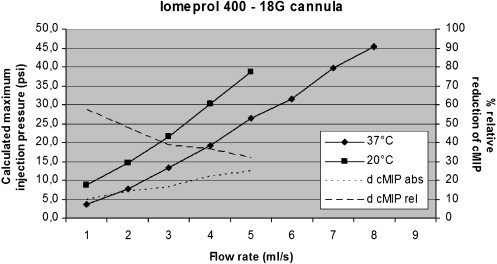
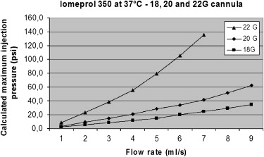
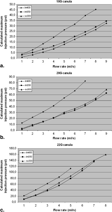
Heating the CM led to reductions in injection pressures ( P < .001). Using constant flow rates, the difference in MIP between 20-gauge and 22-gauge IVCs was higher than that between 20-gauge and 18-gauge IVCs. By heating the CM, the manufacturer’s suggested operating pressure limit was exceeded at higher flow rates, such as with an 18-gauge cannula at 8 mL/s instead of 6 mL/s using warmed iomeprol 400. Even with pressures of up to 159.7 psi, none of the IVCs ruptured.
Conclusions
Heating of CM effectively reduces MIPs using power injection in common IVCs. Although the manufacturer’s suggested MIP was exceeded at higher flow rates, safe CM injection seems to be possible even in small cannulas using power injection. The compilation of the obtained data is meant to serve as guidance for future decisions on parameters of the power injection of iodinated CM.
Modern computed tomographic scanners and examination protocols often require high intravenous iodine delivery rates. Arterial contrast enhancement is directly proportional to the injection flow rate and to the iodine concentration . Higher injection rates of contrast media (CM) result in higher injection pressures in both the dedicated material and patients’ veins. Although the majority of manufacturers offer peripheral intravenous catheters (IVCs) in calibers of 16 gauge and higher, the most commonly used cannula sizes used for CM application in daily clinical routine are 22, 20, and 18 gauge. The preference for these calibers is also reflected by the majority of publications reporting examinations that rely on high-flow injection protocols (eg, coronary computed tomographic angiography or brain perfusion imaging with computed tomography) .
Previous studies have reported on the pressures occurring in IVCs during power injection of unheated CM . Nowadays, virtually every power injector has a CM-heating device. Although it is known that heating CM has a major influence on injection physics , only limited data exist about the effects of heating CM for peripheral intravenous power injection of iodinated CM compared to CM at room temperature.
Get Radiology Tree app to read full this article<
Materials and methods
Get Radiology Tree app to read full this article<
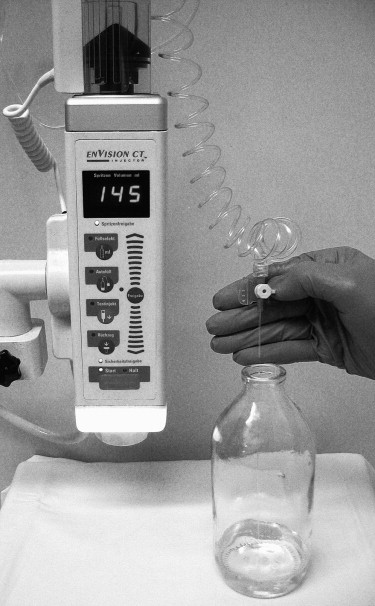
Table 1
Contrast Media Used for Testing
Brand Name Iodine Agent Concentration of Iodine (mg/mL) Viscosity (mPa · s) 37°C 20 °C Solutrast 300 ∗ Iopamidol 300 4.5 8.1 Imeron 350 ∗ Iomeprol 350 7.5 ± 0.6 14.5 ± 1.1 Imeron 400 ∗ Iomeprol 400 12.6 ± 1.1 27.5
Get Radiology Tree app to read full this article<
Get Radiology Tree app to read full this article<
Get Radiology Tree app to read full this article<
Get Radiology Tree app to read full this article<
Table 2
Intravenous Catheters Used for Testing
Name Color Caliber (Gauge) Catheter Length (mm) Outer Diameter (mm) Inner Diameter (mm) MIP (bar/psi) Vasofix Safety ∗ Green 18 45 1.3 0.96 3/43.5 Vasofix Safety ∗ Pink 20 33 1.1 0.76 3/43.5 Vasofix Safety ∗ Blue 22 25 0.9 0.61 3/43.5
MIP, manufacturer’s suggested maximum injection pressure.
Get Radiology Tree app to read full this article<
Get Radiology Tree app to read full this article<
Get Radiology Tree app to read full this article<
Get Radiology Tree app to read full this article<
Get Radiology Tree app to read full this article<
Get Radiology Tree app to read full this article<
Results
Get Radiology Tree app to read full this article<
Table 3
Calculated Maximum Injection Pressures (psi) in the Intravenous Catheters with Three Different Contrast Media
Catheter Flow Rate (mL/s) Solutrast 300 ∗ Minimum Maximum Imeron 350 ∗ Minimum Maximum Imeron 400 ∗ Minimum Maximum 37°C Vasofix Safety † (green, 18 gauge) 1 1.0 1.0 1.0 3.0 2.0 4.0 3.7 3.3 4.3 2 3.3 2.0 4.0 5.3 3.0 8.0 7.7 7.0 9.0 3 5.7 5.7 5.7 8.3 8.3 8.3 13.3 13.3 13.3 4 7.7 8.7 9.7 11.3 11.3 11.3 19.3 19.0 20.0 5 7.7 13.0 18.7 15.0 13.3 17.3 26.3 23.7 28.7 6 16.3 17.7 19.3 20.0 16.0 28.0 31.7 31.7 31.7 7 22.0 22.0 22.0 24.3 21.0 26.0 39.7 37.7 43.7 8 26.7 20.0 30.0 29.0 15.7 35.7 45.3 ‡ 34.7 50.7 9 32.7 29.7 38.7 34.3 17.0 43.0 Vasofix Safety † (pink, 20 gauge) 1 2.0 2.0 2.0 3.0 3.0 3.0 12.3 9.3 18.3 2 8.0 6.0 10.0 9.0 8.0 11.0 22.0 22.0 22.0 3 14.7 12.7 17.7 14.7 14.3 15.3 31.0 29.3 34.3 4 21.0 20.7 21.7 21.0 20.3 21.3 41.3 40.0 43.0 5 30.3 24.7 33.7 28.3 22.3 31.3 54.7 ‡ 52.7 57.7 6 36.7 34.3 40.3 33.7 30.0 37.0 66.7 ‡ 62.7 71.7 7 44.3 ‡ 43.0 47.0 41.3 40.0 43.0 83.0 ‡ 77.7 91.7 8 54.0 ‡ 53.0 56.0 51.7 ‡ 48.7 57.7 9 68.7 ‡ 66.7 71.7 62.7 ‡ 54.0 68.0 Vasofix Safety † (blue, 22 gauge) 1 10.0 9.0 12.0 9.3 9.0 10.0 21.3 20.3 23.3 2 23.3 22.0 24.0 23.0 23.0 23.0 41.0 38.0 45.0 3 42.0 40.7 43.7 38.3 38.3 38.3 62.0 ‡ 60.3 65.3 4 65.3 ‡ 64.7 65.7 55.7 ‡ 52.3 59.3 84.0 ‡ 82.0 86.0 5 87.7 ‡ 81.7 97.7 79.3 ‡ 76.3 85.3 112.3 ‡ 108.7 119.7 6 113.0 ‡ 110.3 115.3 105.3 ‡ 104.0 107.0 7 139.7 ‡ 136.0 142.0 135.7 ‡ 134.0 137.0 8 159.7 ‡ 158.0 161.0 9 20°C Vasofix Safety † (green, 18 gauge) 1 4.3 3.3 5.3 6.3 5.0 9.0 8.7 6.7 10.7 2 8.0 7.3 9.3 10.7 8.3 13.3 14.7 11.3 19.3 3 12.0 8.7 16.7 15.7 15.0 16.0 21.7 19.0 24.0 4 15.0 13.7 17.7 20.3 20.3 20.3 30.3 30.3 30.3 5 19.0 18.0 20.0 26.7 26.7 26.7 38.7 38.0 40.0 6 24.3 24.0 25.0 33.0 29.7 36.7 7 30.3 29.7 30.7 40.0 39.3 40.3 8 38.0 37.3 38.3 9 49.3 ‡ 47.0 51.0 Vasofix Safety † (pink, 20 gauge) 1 5.7 3.3 8.3 10.0 10.0 10.0 13.3 12.7 13.7 2 11.0 9.3 12.3 17.3 17.3 17.3 26.3 24.3 28.3 3 19.0 16.7 23.7 26.3 25.0 28.0 41.3 39.0 46.0 4 28.7 27.7 29.7 34.7 33.3 35.3 55.7 ‡ 54.3 58.3 5 38.7 37.0 40.0 46.7 ‡ 44.7 47.7 6 48.7 ‡ 47.0 51.0 56.7 ‡ 56.7 56.7 7 64.3 ‡ 62.7 67.7 8 77.0 ‡ 76.3 78.3 9 Vasofix Safety † (blue, 22 gauge) 1 10.7 9.3 13.3 18.0 17.0 19.0 29.3 26.7 34.7 2 26.0 24.3 29.3 40.3 39.3 41.3 56.7 ‡ 54.3 58.3 3 45.3 ‡ 44.7 45.7 64.0 ‡ 64.0 64.0 83.0 ‡ 83.0 83.0 4 66.7 ‡ 65.7 68.7 87.0 ‡ 84.3 88.3 5 97.3 ‡ 93.0 102.0 112.3 ‡ 111.7 112.7 6 124.7 ‡ 123.0 127.0 7 8 9
Empty cells indicate an excess of the power injector’s pressure limitation (300 psi).
Get Radiology Tree app to read full this article<
Get Radiology Tree app to read full this article<
Get Radiology Tree app to read full this article<
Get Radiology Tree app to read full this article<
Get Radiology Tree app to read full this article<
Get Radiology Tree app to read full this article<
Get Radiology Tree app to read full this article<
Get Radiology Tree app to read full this article<
Get Radiology Tree app to read full this article<
Discussion
Get Radiology Tree app to read full this article<
Get Radiology Tree app to read full this article<
Get Radiology Tree app to read full this article<
Get Radiology Tree app to read full this article<
Get Radiology Tree app to read full this article<
Get Radiology Tree app to read full this article<
Get Radiology Tree app to read full this article<
Get Radiology Tree app to read full this article<
Get Radiology Tree app to read full this article<
Get Radiology Tree app to read full this article<
Get Radiology Tree app to read full this article<
Conclusion
Get Radiology Tree app to read full this article<
Acknowledgment
Get Radiology Tree app to read full this article<
References
1. Fleischmann D.: How to design injection protocols for multiple detector-row CT angiography (MDCTA). Eur Radiol 2005; 15: pp. E60-E65.
2. Fleischmann D., Kamaya A.: Optimal vascular and parenchymal contrast enhancement: the current state of the art. Radiol Clin North Am 2009; 47: pp. 13-26.
3. Bellomi M., Petralia G., Sonzogni A., et. al.: CT perfusion for the monitoring of neoadjuvant chemotherapy and radiation therapy in rectal carcinoma: initial experience. Radiology 2007; 244: pp. 486-493.
4. Bohner G., Forschler A., Hamm B., et. al.: Quantitative perfusion imaging by multi-slice CT in stroke patients. [article in German] Rofo 2003; 175: pp. 806-813.
5. Feuchtner G.M., Muller S., Bonatti J., et. al.: Sixty-four slice CT evaluation of aortic stenosis using planimetry of the aortic valve area. AJR Am J Roentgenol 2007; 189: pp. 197-203.
6. Herzog C., Zwerner P.L., Doll J.R., et. al.: Significant coronary artery stenosis: comparison on per-patient and per-vessel or per-segment basis at 64-section CT angiography. Radiology 2007; 244: pp. 112-120.
7. Kock M.C., Dijkshoorn M.L., Pattynama P.M., et. al.: Multi-detector row computed tomography angiography of peripheral arterial disease. Eur Radiol 2007; 17: pp. 3208-3222.
8. Litmanovitch D., Zamboni G.A., Hauser T.H., et. al.: ECG-gated chest CT angiography with 64-MDCT and tri-phasic IV contrast administration regimen in patients with acute non-specific chest pain. Eur Radiol 2008; 18: pp. 308-317.
9. Lopes L., Sousa R., Ruivo J., et. al.: The contribution of perfusion CT in stroke. [article in Portuguese] Acta Med Port 2006; 19: pp. 484-488.
10. Matsumoto M., Kodama N., Endo Y., et. al.: Dynamic 3D-CT angiography. AJNR Am J Neuroradiol 2007; 28: pp. 299-304.
11. Mueller J., Jeudy J., Poston R., et. al.: Cardiac CT angiography after coronary bypass surgery: prevalence of incidental findings. AJR Am J Roentgenol 2007; 189: pp. 414-419.
12. Sahani D.V., Kalva S.P., Hahn P.F., et. al.: 16-MDCT angiography in living kidney donors at various tube potentials: impact on image quality and radiation dose. AJR Am J Roentgenol 2007; 188: pp. 115-120.
13. Scheffel H., Leschka S., Plass A., et. al.: Accuracy of 64-slice computed tomography for the preoperative detection of coronary artery disease in patients with chronic aortic regurgitation. Am J Cardiol 2007; 100: pp. 701-706.
14. Schlosser T., Mohrs O.K., Magedanz A., et. al.: Assessment of left ventricular function and mass in patients undergoing computed tomography (CT) coronary angiography using 64-detector-row CT: comparison to magnetic resonance imaging. Acta Radiol 2007; 48: pp. 30-35.
15. Schoellnast H., Deutschmann H.A., Berghold A., et. al.: MDCT angiography of the pulmonary arteries: influence of body weight, body mass index, and scan length on arterial enhancement at different iodine flow rates. AJR Am J Roentgenol 2006; 187: pp. 1074-1078.
16. Setty B.N., Sahani D.V., Ouellette-Piazzo K., et. al.: Comparison of enhancement, image quality, cost, and adverse reactions using 2 different contrast medium concentrations for routine chest CT on 16-slice MDCT. J Comput Assist Tomogr 2006; 30: pp. 818-822.
17. Silvennoinen H.M., Hamberg L.M., Valanne L., et. al.: Increasing contrast agent concentration improves enhancement in first-pass CT perfusion. AJNR Am J Neuroradiol 2007; 28: pp. 1299-1303.
18. Sparacia G., Iaia A., Assadi B., et. al.: Perfusion CT in acute stroke: predictive value of perfusion parameters in assessing tissue viability versus infarction. Radiol Med (Torino) 2007; 112: pp. 113-122.
19. Knopp M., Kauczor H.U., Knopp M.A., et. al.: Effects of viscosity, cannula size and temperature in mechanical contrast media administration in CT and magnetic resonance tomography [article in German]. Rofo 1995; 163: pp. 259-264.
20. Halsell R.D.: Heating contrast media: role in contemporary angiography. Radiology 1987; 164: pp. 276-278.
21. Halsell R.D.: Heating contrast media in a microwave oven. Radiology 1987; 163: pp. 279-280.
22. Schwab S.A., Uder M., Anders K., et. al.: Peripheral intravenous power injection of iodinated contrast media through 22G and 20G cannulas: can high flow rates be achieved safely? A clinical feasibility study. Rofo 2009; 181: pp. 355-361.
23. Carlson J.E., Hedlund L.J., Trenkner S.W., et. al.: Safety considerations in the power injection of contrast media via central venous catheters during computed tomographic examinations. Invest Radiol 1992; 27: pp. 337-340.
24. Gebauer B., Teichgraber U.K., Hothan T., et. al.: Contrast media pressure injection using a portal catheter system—results of an in vitro study. [article in German] Rofo 2005; 177: pp. 1417-1423.
25. Herts B.R., Cohen M.A., McInroy B., et. al.: Power injection of intravenous contrast material through central venous catheters for CT: in vitro evaluation. Radiology 1996; 200: pp. 731-735.
26. Rivitz S.M., Drucker E.A.: Power injection of peripherally inserted central catheters. J Vasc Interv Radiol 1997; 8: pp. 857-863.
27. Ruess L., Bulas D.I., Rivera O., et. al.: In-line pressures generated in small-bore central venous catheters during power injection of CT contrast media. Radiology 1997; 203: pp. 625-629.
28. Salis A.I., Eclavea A., Johnson M.S., et. al.: Maximal flow rates possible during power injection through currently available PICCs: an in vitro study. J Vasc Interv Radiol 2004; 15: pp. 275-281.
29. Sanelli P.C., Deshmukh M., Ougorets I., et. al.: Safety and feasibility of using a central venous catheter for rapid contrast injection rates. AJR Am J Roentgenol 2004; 183: pp. 1829-1834.
30. Williamson E.E., McKinney J.M.: Assessing the adequacy of peripherally inserted central catheters for power injection of intravenous contrast agents for CT. J Comput Assist Tomogr 2001; 25: pp. 932-937.
31. Zamos D.T., Emch T.M., Patton H.A., et. al.: Injection rate threshold of triple-lumen central venous catheters: an in vitro study. Acad Radiol 2007; 14: pp. 574-578.
32. Knollmann F., Schimpf K., Felix R.: Iodine delivery rate of different concentrations of iodine-containing contrast agents with rapid injection. [article in German] Rofo 2004; 176: pp. 880-884.