
Rationale and Objectives
Two-dimensional and three-dimensional (2D-3D) registration for angiographic liver interventions is an unsolved problem mainly because of two reasons. First, a suitable protocol for computed tomography angiography (CTA) to contrast liver arteries is not used in clinical practice. Second, in spite of a valuable body of research results in the neuroradiology community, an adequate registration algorithm that addresses the difficult task of 2D-3D alignment of abdominal vessel structures has not been developed yet.
Materials and Methods
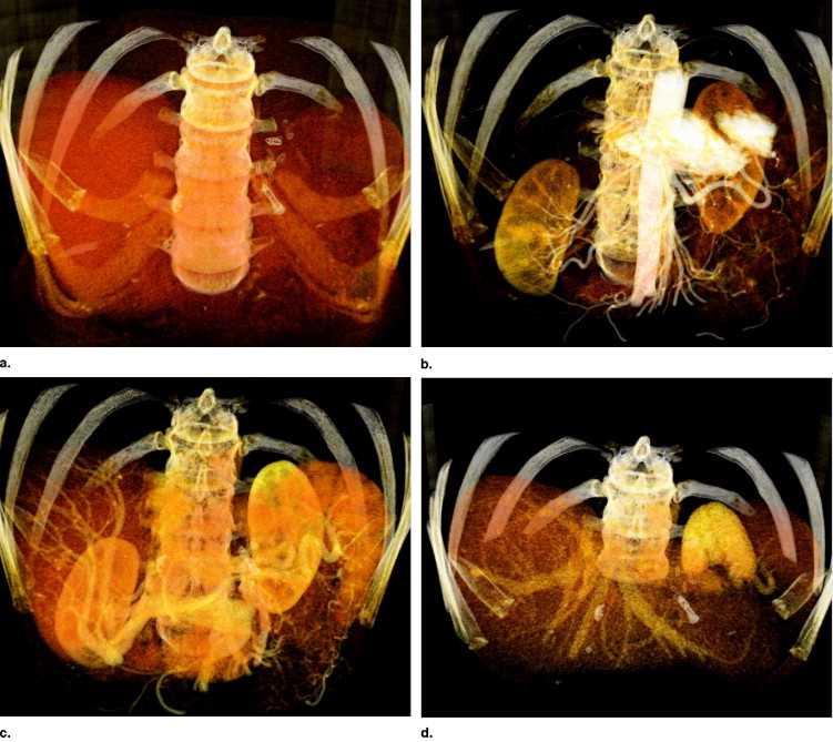
We address the first issue by introducing an angiographic computed tomography (CT) scanning phase. The scan visualizes arteries similar to the vasculature captured with an intraoperative C-arm acquiring digitally subtracted angiograms. Furthermore, we propose a registration algorithm using the new CT phase that aligns arterial structures in two steps: 1) Initialization of one corresponding feature using diameter information and 2) optimization on three rotational and one translational parameters to register vessel structures that are represented as centerline graphs. We form a space of good features by iteratively creating new graphs from projected centerline images and by restricting the correspondence search only on branching points (the vertices) of the vessel tree.
Results
We show convergence and robustness of the proposed algorithm on synthetic data, as well as head phantom and four consistent patient data sets. We compare our results with those of a recently proposed method. Moreover, we evaluate different visualization techniques and show that a transfer of planning information to intraoperative data is a benefit for interventional workflow.
Conclusions
Introducing a new CTA protocol and a two-step 2D-3D registration algorithm, the proposed method creates a strong link between radiologists and interventionalists by bringing preoperative patient and planning information to interventional workflow.
Angiographic imaging is a widely used technique for intravascular interventions. In such treatments a preoperative three-dimensional (3D) dataset is usually acquired for diagnosis and planning. This dataset shows detailed information of the patient’s anatomy. 3D datasets are commonly acquired using computed tomography angiography (CTA). During the intervention, an intraoperative imaging device captures the current state of placed catheter and anatomy of the patient for navigation. In clinical practice, 2D fluoroscopic projections of the region of interest are acquired, which lack spatial resolution compared to the preoperative data sets.
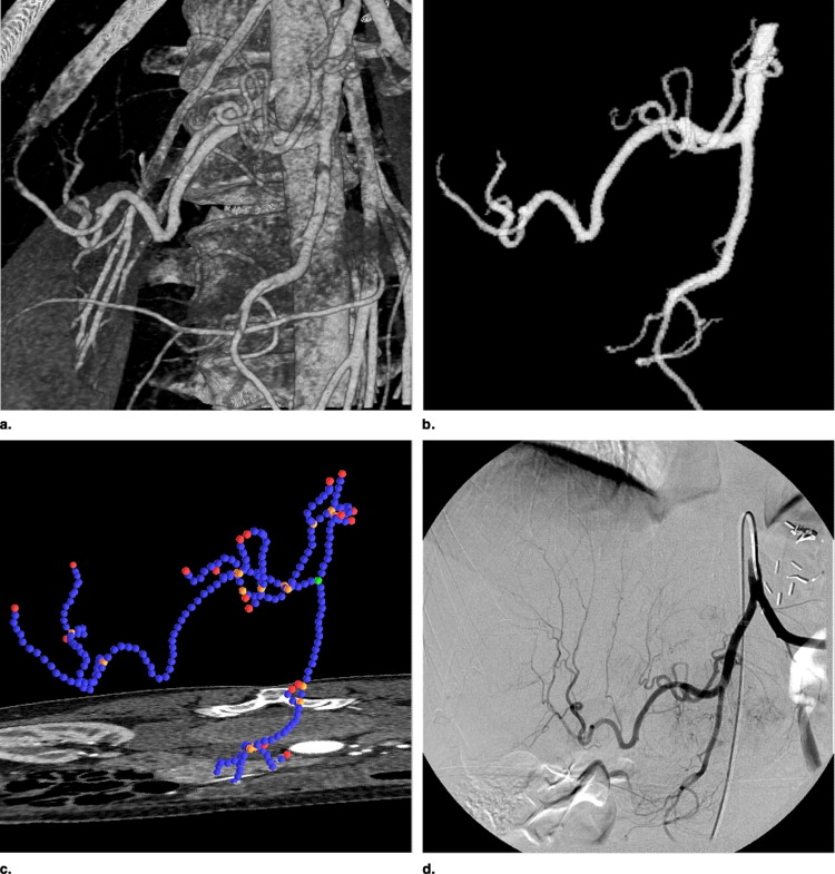
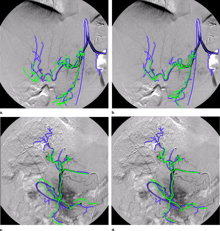
Patients suffering from primary liver cancer are frequently treated with local chemoembolizations (transarterial chemoembolizations). Here, to apply local chemotherapy and to embolize the blood vessels supporting the tumor, a catheter is inserted into the arterial vasculature in the hip region and guided to the tumor’s location using digitally subtracted angiograms (DSAs). The navigation through the vessel system is rather difficult for physicians because of lack of depth perception and information about the tumor’s location, which can only be visualized after the catheter is near the tumor and contrast injections propagate further down the vessel tree. Registering pre- and intraoperative datasets would allow physicians to view the pathology in 3D together with detailed patient anatomy. Moreover, a path through the vessel system (roadmap) can be planned preoperatively in 3D and projected onto the recently acquired two-dimensional (2D) data.
Get Radiology Tree app to read full this article<
Related work
Get Radiology Tree app to read full this article<
Get Radiology Tree app to read full this article<
Get Radiology Tree app to read full this article<
Get Radiology Tree app to read full this article<
Get Radiology Tree app to read full this article<
Get Radiology Tree app to read full this article<
Get Radiology Tree app to read full this article<
Get Radiology Tree app to read full this article<
Get Radiology Tree app to read full this article<
Get Radiology Tree app to read full this article<
Get Radiology Tree app to read full this article<
Get Radiology Tree app to read full this article<
Article organization and contributions
Get Radiology Tree app to read full this article<
Get Radiology Tree app to read full this article<
Get Radiology Tree app to read full this article<
Materials and methods
Protocol for Diagnostic and Interventional CTA
Get Radiology Tree app to read full this article<
Get Radiology Tree app to read full this article<
Method for Bifurcation-Based 2D-3D Registration
Get Radiology Tree app to read full this article<
Preprocessing
Segmentation
Get Radiology Tree app to read full this article<
Extraction of graphs
Get Radiology Tree app to read full this article<
Get Radiology Tree app to read full this article<
Graph representation of vessel centerlines
Get Radiology Tree app to read full this article<
Registration
Get Radiology Tree app to read full this article<
x=PX=K[R|t]X. x
=
PX
=
K
[
R
|
t
]
X
.
P ∈ R 3 × 4 projects a homogeneous 3D point X onto a homogeneous 2D point x and can be decomposed into K (intrinsic parameters) and rotation R , translation t = ( t x , t y , t z ) T (extrinsic parameters). Because the interventional imaging device used (Siemens Axiom Artis) is fully calibrated, K is known. Moreover, distortion has already been compensated for inherently.
Get Radiology Tree app to read full this article<
Get Radiology Tree app to read full this article<
flsq=∑n1i∥xi−ΦK(R,t,Xi)∥2, f
l
s
q
=
∑
i
n
1
‖
x
i
−
Φ
K
(
R
,
t
,
X
i
)
‖
2
,
where Φ K is the projecting function with calibration matrix K . In our case, however, corresponding information is not available.
Get Radiology Tree app to read full this article<
Initialization
Get Radiology Tree app to read full this article<
Get Radiology Tree app to read full this article<
xi=K−1x˜i x
i
=
K
−
1
x
˜
i
For all node coordinates of the 3D centerline graph X̃ i , we apply an initial transformation including primary and secondary angle R̃ and an approximate z-translation t̃ z = (0, 0, STD ) T :
Xi=X˜iR˜+t˜z X
i
=
X
˜
i
R
˜
+
t
˜
z
Naturally, the values of rotation parameters and z-translation are just a rough estimate and subject to further optimization as described in the following section.
Get Radiology Tree app to read full this article<
Registration of t x and t y
Get Radiology Tree app to read full this article<
Geometric optimization of R and t z
Get Radiology Tree app to read full this article<
ficp=∑n2i∥C(G2D,ΦK(R,tz,Xi))−ΦK(R,tz,Xi)∥2, f
i
c
p
=
∑
i
n
2
‖
C
(
G
2
D
,
Φ
K
(
R
,
t
z
,
X
i
)
)
−
Φ
K
(
R
,
t
z
,
X
i
)
‖
2
,
where G 2 D is the 2D vessel graph, X j , j = 1 . . . n 2 are all points representing the 3D vasculature (bifurcations and segment sampling points). f icp has many local minima because projected points of one 3D vessel segment could easily be driven to different, not corresponding 2D vessel segments in the optimization process. Moreover, even with outlier detection via an adaptive distance threshold based on statistical analysis ( ), the cost function would yield wrong alignment because of deformation.
Get Radiology Tree app to read full this article<
Get Radiology Tree app to read full this article<
fbif=∑n3i∥C({vj},ΦK(R,tz,Vi))−ΦK(R,tz,Vi)∥2, f
b
i
f
=
∑
i
n
3
‖
C
(
{
v
j
}
,
Φ
K
(
R
,
t
z
,
V
i
)
)
−
Φ
K
(
R
,
t
z
,
V
i
)
‖
2
,
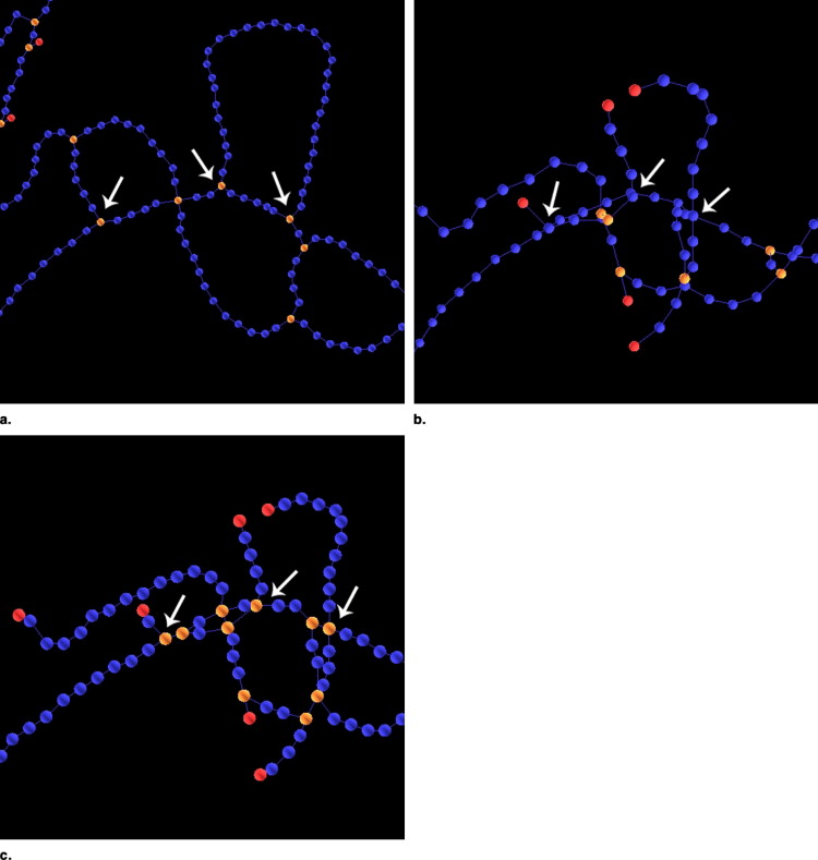
where v 1 , . . . , v__n 2 D and V 1 , . . . , V__n 3 are bifurcation points (the vertices) of the 2D and 3D graphs, respectively. Only inner bifurcations can be used since leaves in the graph account for the end of contrast propagation, which is different in 3D and 2D dataset.
Get Radiology Tree app to read full this article<
Get Radiology Tree app to read full this article<
fextract=∑n4i∥C({vj},ΨK,i(R,tz,G3D))−ΨK,i(R,tz,G3D)∥2, f
e
x
t
r
a
c
t
=
∑
i
n
4
‖
C
(
{
v
j
}
,
Ψ
K
,
i
(
R
,
t
z
,
G
3
D
)
)
−
Ψ
K
,
i
(
R
,
t
z
,
G
3
D
)
‖
2
,
where Ψ = ( vproj1 v
1
p
r
o
j , . . . , vprojn4 v
n4
p
r
o
j ) projects the 3D graph G 3 D with the current parameters R, t z , and extracts a new graph from the projected graph’s centerline image starting at the location of the projected root vertex. The resulting 2D graph’s inner bifurcation list (without leaves) is returned by Ψ.
Get Radiology Tree app to read full this article<
Topological optimization of R and t z
Get Radiology Tree app to read full this article<
ftopo=∑nirbirdi∥C(vj,ΨK,i(R,tz,G3D))−ΨK,i(R,tz,G3D)∥2, f
t
o
p
o
=
∑
i
n
r
i
b
r
i
d
‖
C
(
v
j
,
Ψ
K
,
i
(
R
,
t
z
,
G
3
D
)
)
−
Ψ
K
,
i
(
R
,
t
z
,
G
3
D
)
‖
2
,
where rbi r
i
b is the ratio of the normalized breadth first search values of the current bifurcation vproji v
i
p
r
o
j and the closest bifurcation in the 2D graph or its reciprocal if rbi r
i
b < 1. rdi r
i
d is the ratio of the degrees of vproji v
i
p
r
o
j and the closest 2D bifurcation or its reciprocal if rdi r
i
d < 1.
Get Radiology Tree app to read full this article<
Optimization Scheme
Get Radiology Tree app to read full this article<
Experimental Setup
Get Radiology Tree app to read full this article<
Get Radiology Tree app to read full this article<
Get Radiology Tree app to read full this article<
Get Radiology Tree app to read full this article<
Get Radiology Tree app to read full this article<
Get Radiology Tree app to read full this article<
Results
Registration Accuracy
Get Radiology Tree app to read full this article<
Get Radiology Tree app to read full this article<
Table 1
Standard Deviations (σ) of Rigid Registration of 200 Monte Carlo Simulations. Numbers in bold font show the best result achieved by the three simulations
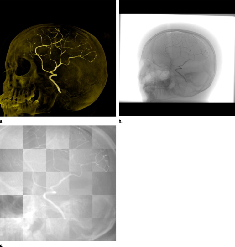
Data Method σ tx [ mm ] σ ty [ mm ] σ tz [ mm ] σα[°] σβ[°] σγ[°] Head simulation M1 0.0004 0.0005 0.0050 0.0028 0.0010 0.0026 M2 — — — — — — Head phantom M1 0.0005 0.0005 0.0069 0.0019 0.0009 0.0022 M2 — — — — — — Patient 1 M11.34871.3982 48.54886.27512.47780.9400 M2 10 17.9463 43.9687 18.8130 19.8789 19.0780 17.4332 M2 5 11.9465 35.882611.7423 7.9779 11.3076 9.9759 Patient 2 M10.14631.26965.01974.59662.5925 1.2467 M2 10 2.6396 2.9281 8.0932 7.9089 6.5415 2.0341 M2 5 1.0204 1.2284 5.5270 5.3732 4.65720.6931 Patient 3 M12.75907.5364 45.05237.78093.9825 7.3726 M2 10 20.7737 45.7128 16.5745 11.7821 17.2824 21.9335 M2 5 19.1786 11.32958.7508 6.0658 9.93464.1008 Patient 4 M16.97311.3264 64.37436.37808.07134.3081 M2 10 43.3558 13.6386 16.8588 20.1722 24.1609 21.4028 M2 5 18.4730 5.509411.0570 6.7126 20.7805 6.2196
Table 2
Root Mean Square Errors ( RMS ) of Rigid Registration of 200 Monte Carlo simulations. Numbers in bold font show the best result achieved by the three simulations
Data Method_RMS tx_ [ mm ]RMS ty [ mm ]RMS tz [ mm ]RMS α[°]RMS β[°]RMS γ[°] Head simulation M1 0.0389 0.2689 2.2302 0.3966 0.0014 0.5100 M2 — — — — — — Head phantom M1 0.1104 0.1787 1.2799 0.5842 0.0291 0.6455 M2 — — — — — — Patient 1 M11.38151.4114 56.24476.87913.61510.9527 M2 10 22.3263 58.1284 19.6391 19.8301 21.5437 21.6254 M2 5 13.2387 40.421912.8111 7.9678 12.7487 11.5099 Patient 2 M1 1.23021.4209 28.40735.06163.8540 2.3298 M2 10 2.6345 4.1985 8.0793 8.9258 6.6079 2.1112 M2 51.0380 2.86835.5190 6.1704 4.67320.7196 Patient 3 M16.55797.8977 66.3731 7.944111.8805 7.4747 M2 10 20.7272 61.2542 17.9872 14.4016 19.0442 29.2579 M2 5 19.3971 11.30379.29256.2510 15.49474.3602 Patient 4 M110.61872.1967 88.9475 8.427116.24055.5228 M2 10 49.3440 14.5086 17.0029 21.6873 25.1797 22.1071 M2 5 19.1812 5.705111.21617.3732 21.6268 6.3191
Get Radiology Tree app to read full this article<
Get Radiology Tree app to read full this article<
Get Radiology Tree app to read full this article<
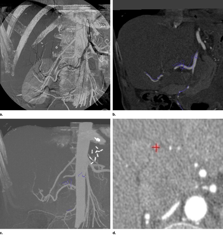
Intraoperative Visualization and Navigation
Get Radiology Tree app to read full this article<
Get Radiology Tree app to read full this article<
Get Radiology Tree app to read full this article<
Discussion
Get Radiology Tree app to read full this article<
Get Radiology Tree app to read full this article<
Get Radiology Tree app to read full this article<
References
1. Zahlten C., Jürgens H., Peitgen H.-O.: Reconstruction of branching blood vessels from CT-data. Eurogr Workshop Vis Scient Comp 1994; pp. 161-168.
2. Kerrien E., Berger M.-O., Maurincomme E., Launay L., Vaillant R., Picard L.: Fully automatic 3d/2d subtracted angiography registration.Proc. Int’l Conf. Medical Image Computing and Computer Assisted Intervention (MICCAI), Vol. 1679 of Lecture Notes in Computer Science.1999.Springerpp. 664-671.
3. Alperin A., Levin D.N., Pelizzari C.A.: Retrospective registration of x-ray angiograms with mr images by using vessels as intrinsic landmarks. J Magnet Reson Imaging 1994; 4: pp. 139-144.
4. Besl P.J., McKay D.: A method for registration of 3-D shapes. IEEE Trans Pattern Anal Mach Intell 1992; 14: pp. 239-256.
5. Zhang Z.: Iterative point matching for registration of free-form curves and surfaces. Int J Comp Vision 1994; 13: pp. 119-152.
6. Feldmar J., Ayache N., Betting F.: 3D-2D projective registration of free-form curves and surfaces.Proc. Int’l Conf. of Computer Vision.1995.IEEEpp. 20-23. 549–556
7. Kita Y., Wilson D., Noble J.: Real-time registration of 3D cerebral vessels to X-ray angiograms.Proc. Int’l Conf. Medical Image Computing and Computer Assisted Intervention (MICCAI), Vol. 1496 of Lecture Notes in Computer Science.1998.Springerpp. 1125-1133.
8. Chan H., Chung A., Yu S., Wells W.: 2D-3D vascular registration between digital subtraction angiographic (DSA) and magnetic resonance angiographic (MRA) images.Proc. of the IEEE International Symposium on Biomedical Imaging, Vol. 1205 of Lecture Notes in Computer Science.2004.IEEEpp. 708-711.
9. Liu A., Bullitt E., Pizer S.: 3D/2D registration via skeletal near projective invariance in tubular objects.Proc. Int’l Conf. Medical Image Computing and Computer Assisted Intervention (MICCAI), Vol. 1496 of Lecture Notes in Computer Science.1998.Springerpp. 952-963.
10. Bullitt E., Liu A., Aylward S., et. al.: Registration of 3d cerebral vessels with 2d digital angiograms: clinical evaluation. Acad Radiol 1999; 6: pp. 539-546.
11. Florin C., Williams J., Khamene A., Paragios N.: Registration of 3D angiographic and X-ray images using sequential monte carlo sampling.Computer Vision for Biomedical Image Applications, First Int’l Workshop, CVBIA ’05, Vol. 3765 of Lecture Notes in Computer Science.2005.Springerpp. 427-436.
12. Hipwell J.H., Penney G.P., McLaughlin R.A., et. al.: Intensity based 2D-3D registration of cerebral angiograms. IEEE Trans Med Imaging 2003; 22: pp. 1417-1426.
13. Chung A.C.S., Wells I.W.M., Norbash A., Grimson W.E.L.: Multi-modal image registration by minimising kullback-leibler distance.Proc. Int’l Conf. Medical Image Computing and Computer Assisted Intervention (MICCAI), Lecture Notes in Computer Science.2002.Springerpp. 525-532.
14. Vermandel M., Betrouni N., Palos G., Gauvrit J.-Y., Vasseur C., Rousseau J.: Registration, matching, and data fusion in 2d/3d medical imaging: Application to DSA and MRA.Proc. Int’l Conf. Medical Image Computing and Computer Assisted Intervention (MICCAI), Vol. 2878 of Lecture Notes in Computer Science.2003.Springerpp. 778-785.
15. Turgeon G.-A., Lehmann G., Guiraudon G., et. al.: 2D-3D registration of coronary angiograms for cardiac procedure planning and guidance. Med Phys 2005; 32: pp. 3737-3749.
16. Yao J., Taylor R.: Assessing accuracy factors in deformable 2d/3d medical image registration using a statistical pelvis model.Proc. Int’l Conf. of Computer Vision (ICCV).2003.IEEE Computer SocietyWashington, DC, USA:pp. 1329.
17. Fleute M., Lavallee S.: Nonrigid 3-d/2-d registration of images using statistical models.Proc. Int’l Conf. Medical Image Computing and Computer Assisted Intervention (MICCAI).1999.SpringerLondon, UK:pp. 138-147.
18. Benameur S., Mignotte M., Parent S., et. al.: 3d/2d registration and segmentation of scoliotic vertebra using statistical models. Comp Med Imaging Graphics 2003; 27: pp. 321-337.
19. Lange T., Wenckebach T.H., Lamecker H., et. al.: Registration of different phases of contrast-enhanced CT/MRI data for computer-assisted liver surgery planning. Int J Med Robot Comp Assisted Surg 2005; 1: pp. 6-20.
20. Charnoz A., Agnus V., Soler L.: Portal vein registration for the follow-up of hepatic tumours.Proc. Int’l Conf. Medical Image Computing and Computer Assisted Intervention (MICCAI), Vol. 3216 of Lecture Notes in Computer Science.2004.Springerpp. 878-886.
21. Charnoz A., Agnus V., Malandain G., Forest C., Tajine M., Soler L.: Liver registration for the follow-up of hepatic tumors.Proc. Int’l Conf. Medical Image Computing and Computer Assisted Intervention (MICCAI), Vol. 3750 of Lecture Notes in Computer Science.2005.Springerpp. 155-162.
22. Charnoz A., Agnus V., Malandain G., Nicolau S., Tajine M., Soler L.: Design of robust vascular tree matching: validation on liver.Proc. Int’l Conf. Information Processing in Medical Imaging (IPMI), Vol. 3565 of Lecture Notes in Computer Science.2005.Springerpp. 443-455.
23. Aylward S., Jomier J., Weeks S., et. al.: Registration and analysis of vascular images. S. Int J Comp Vis 2003; 55: pp. 123-138.
24. Aylward S., Jomier J.: Rigid and deformable vasculature-to-image registration: A hierarchical approach.Proc. Int’l Conf. Medical Image Computing and Computer Assisted Intervention (MICCAI), Vol. 3216 of Lecture Notes in Computer Science.2004.Springerpp. 829-836.
25. Jomier J., Bullitt E., van Horn M., Pathak C., Aylward S.: 3d/2d model-to-image registration applied to tips surgery.Proc. Int’l Conf. Medical Image Computing and Computer Assisted Intervention (MICCAI), Vol. 4191 of Lecture Notes in Computer Science.2006.Springerpp. 662-670.
26. Perona P., Malik J.: Scale-space and edge detection using anisotropic diffusion. Intell 1990; 12: pp. 629-639.
27. Gonzalez R.C., Woods R.E.: Digital image processing.2002.Prentice HallNJ
28. Frangi A.F., Niessen W.J., Vincken K.L., Viergever M.A.: Multiscale vessel enhancement filtering.Proc. Int’l Conf. Medical Image Computing and Computer Assisted Intervention (MICCAI), Vol. 1496 of Lecture Notes in Computer Science.1998.Springerpp. 130-137.
29. Palágyi K., Sorantin E., Balogh E., Kuba A., Halmai C., Erdöhelyi B., Hausegger K.: A sequential 3d thinning algorithm and its medical applications.Proc. Int’l Conf. Information Processing in Medical Imaging (IPMI), Vol. 2028 of Lecture Notes in Computer Science.2001.Springerpp. 409-415.
30. Press W., Teukolsky S., Vetterling W., et. al.: Numerical recipes in C.1993.Cambridge University PressNew York
31. Penney G.P., Weese J., Little J.A., et. al.: A comparison of similarity measures for use in 2D-3D medical image registration. IEEE Trans Med Imaging 1998; 17: pp. 586-595.
32. Tory M.: Mental registration of 2D and 3D visualizations (an empirical study).Proc IEEE Visualiz Conf.2003.pp. 49.