
Rationale and Objectives
Current quantitative morphometric methods of vertebral fracture detection lack specificity, particularly with mild fractures. We use more detailed shape and texture information to develop quantitative classifiers.
Materials and Methods
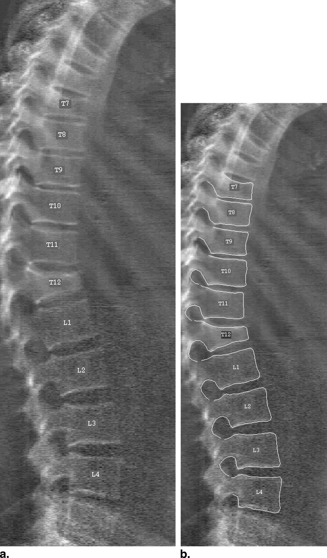
The detailed shape and appearance of vertebrae on 360 lateral dual energy x-ray absorptiometry scans were statistically modeled, thus producing a set of shape and appearance parameters for each vertebra. The vertebrae were given a “gold standard” classification using a consensus reading by two radiologists. Linear discriminants were trained on the vertebral shape and appearance parameters.
Results
The appearance-based classifiers gave significantly better specificity than shape-based methods in all regions of the spine (overall specificity 92% at a sensitivity of 95%), while using the full shape parameters slightly improved specificity in the thoracic spine compared with using three standard height ratios. The main improvement was in the detection of mild fractures. Performance varied over different regions of the spine. False-positive rates at 95% sensitivity for the lumbar, mid-thoracic (T12-T10) and upper thoracic (T9-T7) regions were 2.9%, 14.6%, and 5.5%, respectively, compared with 6.4%, 32.6%, and 21.1% for three-height morphometry.
Conclusion
The appearance and shape parameters of statistical models could provide more powerful quantitative classifiers of osteoporotic vertebral fracture, particularly mild fractures. False positive rates can be substantially reduced at high sensitivity by using an appearance-based classifier, because this can better distinguish between mild fractures and some kinds of non-fracture shape deformities.
Osteoporosis is a progressive skeletal disease characterized by low bone mass and structural deterioration of bone tissue, leading to bone fragility and an increased susceptibility to fractures, especially of the hip, spine, and wrist. Vertebral fractures are the most common, and occur in younger patients. The presence of vertebral fractures significantly increases the risk of further vertebral and nonvertebral fractures ( ). The presence of even one vertebral fracture increases the risk of any subsequent fracture fivefold ( ), and the risk of a subsequent hip fracture is doubled ( ). The accurate identification of prevalent vertebral fractures is therefore clinically important, and the detection of incident vertebral fractures is relevant in evaluating the efficacy of new therapies for osteoporosis.
Vertebral Fracture Detection
There is no precise definition of exactly what constitutes a vertebral fracture, but a variety of methods describing such fractures have been developed ( ). These include semiquantitative methods involving some subjective judgment by an expert radiologist ( ) and fully quantitative morphometric methods ( ). The latter require the manual annotation of six (or more) points on each vertebra. The manual marking is time consuming and may be imprecise.
Get Radiology Tree app to read full this article<
Get Radiology Tree app to read full this article<
Materials and methods
Segmentation
Get Radiology Tree app to read full this article<
Data: DXA Images
Get Radiology Tree app to read full this article<
Get Radiology Tree app to read full this article<
Get Radiology Tree app to read full this article<
Get Radiology Tree app to read full this article<
Classification of Vertebrae
Get Radiology Tree app to read full this article<
Discriminant Analysis
Get Radiology Tree app to read full this article<
x≈T(x¯M+Φb) x
≈
T
(
x
¯
M
+
Φ
b
)
where x¯M x
¯
M is the mean aligned shape (in the model frame), Φ is the orthogonal basis matrix consisting of the column-wise concatenation of the eigenvectors, b is the vector of shape parameters, and T is a similarity transform representing the shape’s pose parameters (positional offset, isotropic scaling and rotation).
Get Radiology Tree app to read full this article<
Get Radiology Tree app to read full this article<
Get Radiology Tree app to read full this article<
w=(PTP)−1PTy w
=
(
P
T
P
)
−
1
P
T
y
Get Radiology Tree app to read full this article<
Get Radiology Tree app to read full this article<
Get Radiology Tree app to read full this article<
Get Radiology Tree app to read full this article<
rmid=Hm/Hp,rwedge=Ha/Hp, r
m
i
d
=
H
m
/
H
p
,
r
w
e
d
g
e
=
H
a
/
H
p
,
where H m , H a are the middle and anterior heights, respectively. As a second baseline comparison, we used a hybrid morphometric method in the more standard manner, using these same ratios: the Eastell-Melton ( ) method for the mid-height and wedge ratios and the McCloskey method’s ( ) crush ratio r crush . We calculated the mean and standard deviation of each of the three ratios over the normal population (excluding any vertebrae classified as deformed). A vertebra was then classified as fractured if any of the three ratios was less than X standard deviations below the normal mean. X was varied to generate derived receiver operating characteristic (ROC) curves. We refer to this method below as Eastell-McCloskey hybrid.
Get Radiology Tree app to read full this article<
Experiments
Get Radiology Tree app to read full this article<
L(frac)i=(1+exp(−w.pi))−1 L
i
(
f
r
a
c
)
=
(
1
+
exp
(
−
w
.
p
i
)
)
−
1
Get Radiology Tree app to read full this article<
Get Radiology Tree app to read full this article<
Get Radiology Tree app to read full this article<
Get Radiology Tree app to read full this article<
Get Radiology Tree app to read full this article<
Get Radiology Tree app to read full this article<
(|Nab−Nba|−1)2Nab+Nba (
|
N
a
b
−
N
b
a
|
−
1
)
2
N
a
b
+
N
b
a
Get Radiology Tree app to read full this article<
Get Radiology Tree app to read full this article<
Results
Get Radiology Tree app to read full this article<
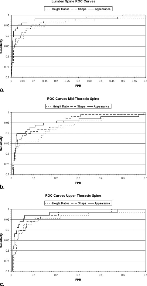
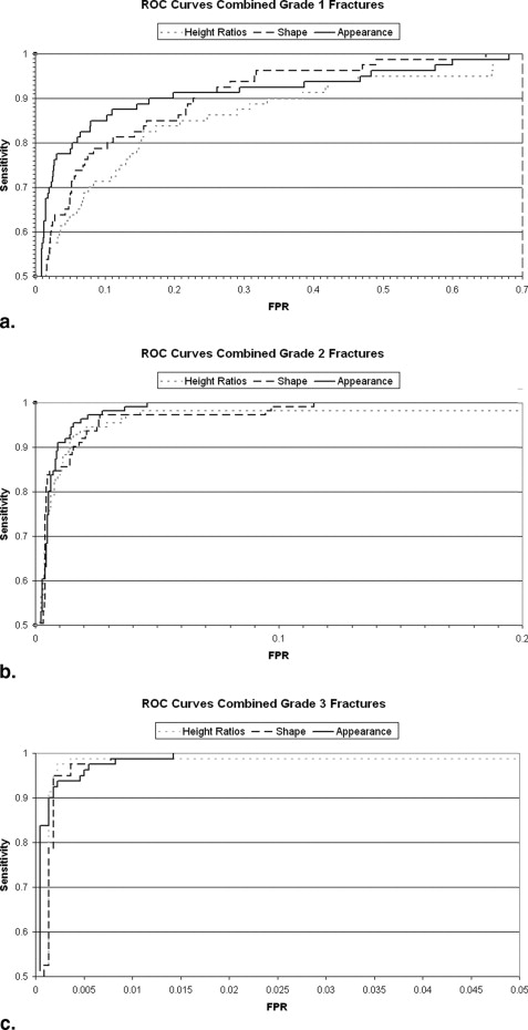
Table 1
Area Under ROC Curve for Various Spine Regions or Fracture Grades with the Four Classifier Types
Shape Parameter Classifier Appearance Parameter Classifier Height Ratios Classifier Hybrid Eastell-McCloskey L1-L4 0.9809 0.9847 0.9713 0.9755 T12-T10 0.9680 0.9681 0.9564 0.9574 T9-T7 0.9777 0.9848 0.9700 0.9655 All combined 0.9756 0.9789 0.9651 0.9664 All grade 1 0.9288 0.9358 0.8966 0.9069 All grade 2 0.9926 0.9955 0.9906 0.9870 All grade 3 0.9987 0.9991 0.9981 0.9973
Note the height ratios classifier is a linear discriminant trained on the joint three-height distribution.
Table 2
False-Positive Rate (FPR) at Varying Sensitivities for the Three Spinal Regions and Four Classification Methods, and Discriminant Training via Geman-McClure Robust Function
Spinal Region Classifier FPR at 90% Sensitivity FPR at 95% Sensitivity FPR at 98% Sensitivity L4-L1 Shape 4.2% 9.2% 28.6% Appearance 1.0% 2.9% 10.5% Height ratios 5.5% 14.9% 37.3% Hybrid Eastell-McCloskey 3.3% 6.4% 36.4% T12-T10 Shape 8.7% 23.3% 30.9% Appearance 6.3% 14.6% 39.9% Height ratios 15.2% 29.9% 46.0% Hybrid Eastell-McCloskey 6.0% 32.6% 58.8% T9-T7 Shape 6.2% 10.7% 21.1% Appearance 2.6% 5.5% 15.8% Height ratios 5.5% 12.1% 32.3% Hybrid Eastell-McCloskey 10.3% 21.1% 32.2%
Table 3
False-Positive Rate (FPR) at Varying Sensitivities for the Three Spinal Regions and Three Linear Discriminant Methods, with Discriminants Trained by Least Squares Regression
Spinal Region Classifier FPR at 90% Sensitivity FPR at 95% Sensitivity FPR at 98% Sensitivity L4-L1 Shape 4.4% 10.5% 32.2% Appearance 1.0% 4.4% 10.8% Height ratios 6.0% 16.0% 38.3% T12-T10 Shape 8.0% 23.9% 34.1% Appearance 6.4% 16.2% 53.4% Height ratios 16.1% 29.9% 47.5% T9-T7 Shape 6.4% 10.5% 21.7% Appearance 3.1% 7.0% 17.10% Height ratios 5.5% 12.3% 34.6%
Table 4
McNemar χ21 χ
1
2 test statistic for pairwise specificity comparisons at the given sensitivities. The brackets indicate that the first classifier appears better than the second
Spinal region Classifier Comparison χ 2 at 93% Sensitivity χ 2 at 95% Sensitivity χ 2 at 97% Sensitivity L4-L1 Height vs shape 4.74 24.27 5.26 Height vs appearance 52.51 85.75 67.93 Shape vs appearance 40.16 44.08 53.12 Eastell-McCloskey vs height (17.05) (46.23) (17.93) T12-T10 Height vs shape 3.6 17.31 23.90 Height vs appearance 75.0 70.47 33.37 Shape vs appearance 60.56 35.91 4.70 Eastell-McCloskey vs height 3.93 4.17 2.47 T9-T7 Height vs shape 5.76 2.19 35.83 Height vs appearance 18.67 24.02 82.38 Shape vs appearance 9.97 17.82 29.82 Eastell-McCloskey vs height 11.52 28.80 0.11
Get Radiology Tree app to read full this article<
Get Radiology Tree app to read full this article<
Get Radiology Tree app to read full this article<
Discussion
Get Radiology Tree app to read full this article<
Get Radiology Tree app to read full this article<
Get Radiology Tree app to read full this article<
Get Radiology Tree app to read full this article<
Get Radiology Tree app to read full this article<
Get Radiology Tree app to read full this article<
Get Radiology Tree app to read full this article<
Get Radiology Tree app to read full this article<
Conclusions
Get Radiology Tree app to read full this article<
Acknowledgments
Get Radiology Tree app to read full this article<
Appendix 1
Fitting the categorical regression model
Get Radiology Tree app to read full this article<
Get Radiology Tree app to read full this article<
Get Radiology Tree app to read full this article<
Get Radiology Tree app to read full this article<
Get Radiology Tree app to read full this article<
Get Radiology Tree app to read full this article<
Get Radiology Tree app to read full this article<
Appendix 2
Appearance model form
Get Radiology Tree app to read full this article<
Get Radiology Tree app to read full this article<
Get Radiology Tree app to read full this article<
Get Radiology Tree app to read full this article<
Appendix 3
Predicted posterior height
Get Radiology Tree app to read full this article<
Get Radiology Tree app to read full this article<
References
1. Melton L.J., Atkinson E.J., Cooper C., et. al.: Vertebral fractures predict subsequent fractures. Osteoporosis Int 1999; 10: pp. 214-221.
2. Black D.M., Arden N.K., Palermo L., et. al.: Prevalent vertebral deformities predict hip fractures and new vertebral deformities but not wrist fractures. J Bone Miner Res 1999; 14: pp. 821-828.
3. Guermazi A., Mohr A., Grigorian M., et. al.: Identification of vertebral fractures in osteoporosis. Semin Musculoskel Radiol 2002; 6: pp. 241-252.
4. Genant H.K., Wu C.Y., van Kuijk C., et. al.: Vertebral fracture assessment using a semi-quantitative technique. J Bone Miner Res 1993; 8: pp. 1137-1148.
5. Black D.M., Cummings S.R., Stone K., et. al.: A new approach to defining normal vertebral dimensions. J Bone Miner Res 1991; 6: pp. 883-892.
6. Eastell R., Cedel S.L., Wahner H.W., et. al.: Classification of vertebral fractures. J Bone Miner Res 1991; 6: pp. 207-215.
7. McCloskey E., Spector T., Eyres K., et. al.: The assessment of vertebral deformity: a method for use in population studies and clinical trials. Osteoporosis Int 1993; 3: pp. 138-147.
8. Wu C.Y., Li J., Jergas M., et. al.: Semiquantitative and quantitative assessment of incident fractures: comparison of methods. J Bone Miner Res 1994; 9: pp. 157. [abstract]
9. Black D., Palermo L., Nevitt M.C., et. al.: Comparison of methods for defining prevalent vertebral deformities: The study of osteoporotic fractures. J Bone Miner Res 1995; 10: pp. 890-902.
10. Jiang G., Eastell R., Barrington N.A., et. al.: Comparison of methods for the visual identification of prevalent vertebral fracture in osteoporosis. Osteoporosis Int 2004; 15: pp. 887-896.
11. Smyth P.P., Taylor C.J., Adams J.E.: Vertebral shape: automatic measurement with active shape models. Radiology 1999; 211: pp. 571-578.
12. Howe B., Gururajan A., Sari-Sarraf H., et. al.: Hierarchical segmentation of cervical and lumbar vertebrae using a customized generalized Hough transform and extensions to active appearance models. Proc IEEE 6th SSIAI 2004; pp. 182-186.
13. de Bruijne M., Nielsen M.: Image segmentation by shape particle filtering. Proc Int Conf Pattern Recognition 2004; pp. 722-725.
14. Roberts M., Cootes T., Adams J.: Vertebral morphometry: semiautomatic determination of detailed shape from dual-energy X-ray absorptiometry images using active appearance models. Invest Radiol 2006; 41: pp. 849-859.
15. Blake G.M., Rea J.A., Fogelman I.: Vertebral morphometry studies using dual-energy X-ray absorptiometry. Semin Nucl Med 1997; 27: pp. 276-290.
16. Rea J.A., Li J., Blake G.M., et. al.: Visual assessment of vertebral deformity by x-ray absorptiometry: a highly predictive method to exclude vertebral deformity. Osteoporosis Int 2000; 11: pp. 660-668.
17. Ferrar L., Jiang G., Eastell R., et. al.: Visual identification of vertebral fractures in osteoporosis: using morphometric x-ray absorptiometry. J Bone Miner Res 2003; 18: pp. 933-938.
18. Binkley N., Krueger D., Gangnon R., et. al.: Lateral vertebral assessment: a valuable technique to detect clinically significant vertebral fractures. Osteoporos Int 2005; 16: pp. 1513-1518.
19. McCloskey E., Selby P., de Takats D., et. al.: Effects of clodronate on vertebral fracture risk in osteoporosis: a 1-year interim analysis. Bone 2001; 28: pp. 310-315.
20. Cootes T.F., Taylor C.J.: Statistical models of appearance for medical image analysis and computer vision. Proc SPIE Med Imaging 2001; 3: pp. 138-147.
21. Cootes T.F., Edwards G.J., Taylor C.J.: Active appearance models. Proc 5th Eur Conf Computer Vision 1998; 2: pp. 484-498.
22. Ferrar L., Jiang G., Adams J., et. al.: Identification of vertebral fractures: an update. Osteoporosis Int 2005; 16: pp. 717-728.
23. McNemar Q.: Note on the sampling error of the difference between correlated proportions or percentages. Psychometrika 1947; 12: pp. 153-157.
24. Zweig M.H., Campbell G.: Receiver-operating characteristic (ROC) Plots: a fundamental evaluation tool in clinical medicine. Clin Chem 1993; 39: pp. 561-577.
25. de Bruijne M., Lund M., Tanko L., et. al.: Quantitative vertebral morphometry using neighbor-conditional shape models. Proc 9th MICCAI Conference 2006; 1: pp. 1-8.
26. Rea J., Steiger P., Li J., et. al.: Morphometric x-ray absorptiometry: reference data for vertebral dimensions. J Bone Miner Res 1998; 13: pp. 464-474.