
Rationale and Objectives
The aim of this study was too assess magnetic resonance imaging (MRI) radiofrequency (RF)–related heating of conductive wire coils used in magnetically steerable endovascular catheters.
Materials and Methods
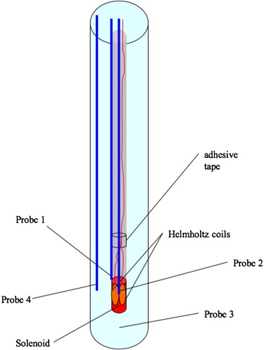
A three-axis microcoil was fabricated onto a 1.8Fr catheter tip. In vitro testing was performed on a 1.5-T MRI system using an agarose gel–filled vessel phantom, a transmit-receive body RF coil, a steady-state free precession pulse sequence, and a fluoroptic thermometry system. Temperature was measured without simulated blood flow at varying distances from the magnet isocenter and at varying flip angles. Additional experiments were performed with laser-lithographed single-axis microcoil-tipped microcatheters in air and in a saline bath with varied grounding of the microcoil wires. Preliminary in vivo evaluation of RF heating was performed in pigs at 1.5 T with coil-tipped catheters in various positions in the common carotid arteries with steady-state free precession pulse sequence on and off and under physiologic-flow and zero-flow conditions.
Results
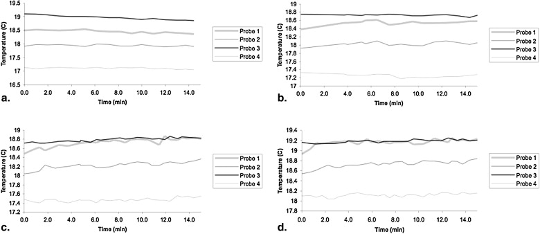
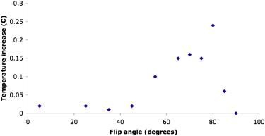
In tissue-mimicking agarose gel, RF heating resulted in a maximal temperature increase of 0.35°C after 15 minutes of imaging, 15 cm from the magnet isocenter. For a single-axis microcoil, maximal temperature increases were 0.73°C to 1.91°C in air and 0.45°C to 0.55°C in saline. In vivo, delayed contrast-enhanced MRI revealed no evidence of vascular injury, and histopathologic sections from the common carotid arteries confirmed the lack of vascular damage.
Conclusions
Microcatheter tip microcoils for endovascular catheter steering in MRI experience minimal RF heating under the conditions tested. These data provide the basis for further in vivo testing of this promising technology for endovascular interventional MRI.
Current applied to copper microcoils placed at the tip of an endovascular device can be used to steer a catheter within a clinical magnetic resonance (MR) imaging (MRI) scanner . The current applied induces a magnetic moment within the coils at the catheter tip, which experiences a torque in the presence of the scanner main magnetic field, producing remotely controllable deflections that can be used for navigating vessel turns and branches or holding the catheter tip in a specific orientation. The electric currents required to generate the desired magnetic moments, however, can generate enough heat through resistive dissipation to cause temperatures unsafe for blood or vascular walls. We have shown that undesirable temperature increases due to resistive heating can be mitigated using high–thermal conductivity material for the catheter tip and flowing saline coolant through the catheter lumen (see the accompanying report, “Steerable Catheter Microcoils for Interventional MRI: Reducing Resistive Heating,” in this issue [3]).
Undesirable heating, however, may also occur in a long wire (eg, a guidewire) running down the lumen of the catheter because of field coupling with radiofrequency (RF) magnetic fields used for MRI through the “antenna effect” . Metallic devices used in MRI-guided endovascular procedures, such as guidewires, braided catheters, catheter tracking coils, or intravascular imaging coils, even if not ferromagnetic, have the potential to interact with the time-varying RF electromagnetic fields from the RF transmitter, causing heating in and near the device and thus posing a hazard to the patient. The concentration of RF power within such devices may cause a significant increase in the specific absorption rate (SAR) of the surrounding tissue, potentially resulting in excessive local temperature rise and burns .
Get Radiology Tree app to read full this article<
Get Radiology Tree app to read full this article<
Get Radiology Tree app to read full this article<
Get Radiology Tree app to read full this article<
Get Radiology Tree app to read full this article<
Materials and methods
Handmade Coil Testing
Device construction
Get Radiology Tree app to read full this article<
Temperature measurements in the MR system
Get Radiology Tree app to read full this article<
Get Radiology Tree app to read full this article<
Get Radiology Tree app to read full this article<
Laser-lithographed Coil Testing
Device construction
Get Radiology Tree app to read full this article<
RF Heating evaluation
Get Radiology Tree app to read full this article<
Get Radiology Tree app to read full this article<
Preliminary in vivo evaluation at 1.5 T
Get Radiology Tree app to read full this article<
Get Radiology Tree app to read full this article<
Get Radiology Tree app to read full this article<
Get Radiology Tree app to read full this article<
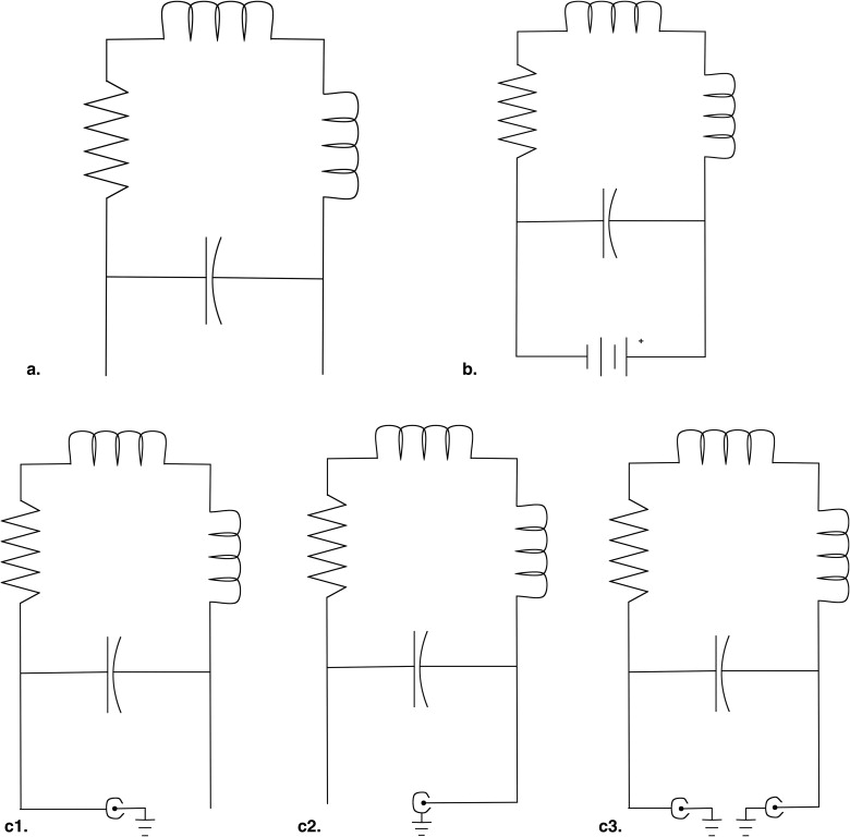
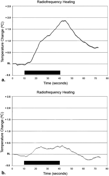
Table 1
Temperature Rise Measured by Luxtron Fiber Optic Probe Mounted on Single-axis Coil-tipped Catheter Placed in the Groove of a 1.5-T Magnet Dovetail (Maximally Offset From the Center of the Bore by 27.4 cm) Under Various Grounding and Filtration Schemes
SAR (W/kg) Acquisition Time (seconds) Environment Grounding or Filtration Temperature Rise (°C) 4 30 Air Catheter wires not connected (“floating”) ( Fig 4 a) 1.86 4 30 Air Short circuit; power supply on at zero current ( Fig 4 b) 0.85 4 30 Air Short circuit; power supply turned off ( Fig 4 b) 0.89 4 30 Air Inner wire grounded and outer layer BNC floating ( Fig 4 c1) 1.53 4 30 Air Inner wire floating and outer layer BNC grounded ( Fig 4 c2) 0.73 4 30 Air Inner wire and outer layer BNC grounded ( Fig 4 c3) 1.91 4 30 Saline Inner wire grounded and outer layer BNC floating ( Fig 4 c1) 0.45 4 30 Saline Inner wire and outer layer BNC grounded ( Fig 4 c3) 0.55
Acquisition time consists of 10 seconds without imaging, followed by 30 seconds of steady-state free precession imaging, followed by 30 seconds without imaging.
BNC, Bayonet Neill-Concelman; SAR, specific absorption rate.
Get Radiology Tree app to read full this article<
Get Radiology Tree app to read full this article<
Get Radiology Tree app to read full this article<
Results
RF Heating of Handmade Coils in Agarose Gel Phantom
Get Radiology Tree app to read full this article<
Get Radiology Tree app to read full this article<
Get Radiology Tree app to read full this article<
Get Radiology Tree app to read full this article<
RF Heating of Laser-lithographed Coils in Air and Saline
Get Radiology Tree app to read full this article<
Get Radiology Tree app to read full this article<
In Vivo Results
Get Radiology Tree app to read full this article<
Discussion
Get Radiology Tree app to read full this article<
Get Radiology Tree app to read full this article<
Get Radiology Tree app to read full this article<
Get Radiology Tree app to read full this article<
Get Radiology Tree app to read full this article<
Get Radiology Tree app to read full this article<
Get Radiology Tree app to read full this article<
Get Radiology Tree app to read full this article<
Conclusions
Get Radiology Tree app to read full this article<
Get Radiology Tree app to read full this article<
References
1. Roberts T.P., Hassenzahl W.V., Hetts S.W., et. al.: Remote control of catheter tip deflection: an opportunity for interventional MRI. Magn Reson Med 2002; 48: pp. 1091-1095.
2. Settecase F., Sussman M.S., Wilson M.W., et. al.: Magnetically-assisted remote control (MARC) steering of endovascular catheters for interventional MRI: a model for deflection and design implications. Med Phys 2007; 34: pp. 3135-3142.
3. Bernhardt A., Wilson M.W., Settecase F., et. al.: Steerable catheter microcoils for interventional MRI: reducing resistive heating. Acad Radiol 2011; 18: pp. 270-276.
4. Ladd M.E., Quick H.H.: Reduction of resonant RF heating in intravascular catheters using coaxial chokes. Magn Reson Med 2000; 43: pp. 615-619.
5. Balaris C.: Antenna theory: analysis and design.1982.John WileyNew York
6. Nitz W.R., Oppelt A., Renz W., et. al.: On the heating of linear conductive structures as guide wires and catheters in interventional MRI. J Magn Reson Imaging 2001; 13: pp. 105-114.
7. Konings M.K., Bartels L.W., Smits H.F., et. al.: Heating around intravascular guidewires by resonating RF waves. J Magn Reson Imaging 2000; 12: pp. 79-85.
8. Dempsey M.F., Condon B., Hadley D.M.: Investigation of the factors responsible for burns during MRI. J Magn Reson Imaging 2001; 13: pp. 627-631.
9. Yeung C.J., Susil R.C., Atalar E.: RF heating due to conductive wires during MRI depends on the phase distribution of the transmit field. Magn Reson Med 2002; 48: pp. 1096-1098.
10. Yeung C.J., Atalar E.: RF transmit power limit for the barewire loopless catheter antenna. J Magn Reson Imaging 2000; 12: pp. 86-91.
11. Qiu B., Yeung C.J., Du X., et. al.: Development of an intravascular heating source using an MR imaging guidewire. J Magn Reson Imaging 2002; 16: pp. 716-720.
12. Shellock F.G.: Radiofrequency energy-induced heating during MR procedures: a review. J Magn Reson Imaging 2000; 12: pp. 30-36.
13. Shellock F.G.: Magnetic resonance safety update 2002: implants and devices. J Magn Reson Imaging 2002; 16: pp. 485-496.
14. Athey T.W.: Current FDA guidance for MR patient exposure and considerations for the future. Ann N Y Acad Sci 1992; 649: pp. 242-257.
15. Wildermuth S., Dumoulin C.L., Pfammatter T., et. al.: MR-guided percutaneous angioplasty: assessment of tracking safety, catheter handling and functionality. Cardiovasc Intervent Radiol 1998; 21: pp. 404-410.
16. Yeung C.J., Susil R.C., Atalar E.: RF safety of wires in interventional MRI: using a safety index. Magn Reson Med 2002; 47: pp. 187-193.
17. Center for Devices and Radiological Health: Guidance for the submission of premarket notifications for magnetic resonance diagnostic devices.1998.US Food and Drug AdministrationRockville, MD 21
18. International Electrotechnical Commission: International standard, medical equipment—part 2: particular requirements for the safety of magnetic resonance equipment for medical diagnosis.2nd rev ed2002.International Electrotechnical CommissionGeneva, Switzerland
19. Liu C.Y., Farahani K., Lu D.S., et. al.: Safety of MRI-guided endovascular guidewire applications. J Magn Reson Imaging 2000; 12: pp. 75-78.
20. Quick H.H., Ladd M.E., von Schulthess G.K., et. al.: Heating effects of an intravascular imaging catheter.1997.MAGMABrussels, Belgium
21. Settecase F, Sussman MS, Wilson MW, et al. Evaluation of RF and resistive heating due to magnetically-assisted remote control (MARC) steering coils for endovascular interventional MRI. Presented at: 16th Annual Meeting of the ISMRM; Toronto, ON, Canada; 2008.
22. Weiss S., Vernickel P., Schaeffter T., et. al.: Transmission line for improved RF safety of interventional devices. Magn Reson Med 2005; 54: pp. 182-189.
23. Armenean C., Perrin E., Armenean M., et. al.: RF-induced temperature elevation along metallic wires in clinical magnetic resonance imaging: influence of diameter and length. Magn Reson Med 2004; 52: pp. 1200-1206.