
Rationale and Objectives
The aims of this study were to assess resistive heating of microwires used for remote catheter steering in interventional magnetic resonance imaging and to investigate the use of alumina to facilitate heat transfer to saline flowing in the catheter lumen.
Materials and Methods
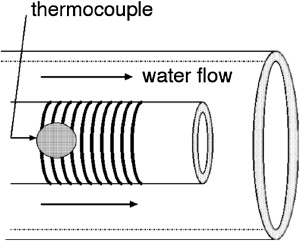
A microcoil was fabricated using a laser lathe onto polyimide-tipped or alumina-tipped endovascular catheters. In vitro testing was performed on a 1.5-T magnetic resonance system using a vessel phantom, body radiofrequency coil, and steady-state pulse sequence. Resistive heating was measured with water flowing over a polyimide-tip catheter or saline flowing through the lumen of an alumina-tip catheter. Preliminary in vivo testing in porcine common carotid arteries was conducted with normal blood flow or after arterial ligation when current was applied to an alumina-tip catheter for up to 5 minutes.
Results
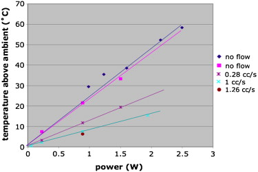
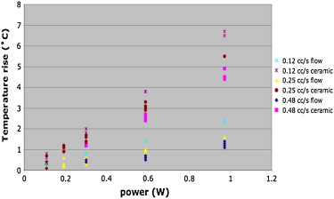
After application of up to 1 W of direct current power, clinically significant temperature increases were noted with the polyimide-tip catheter: 23°C/W at zero flow, 13°C/W at 0.28 cm 3 /s, and 7.9°C/W at 1 cm 3 /s. Using the alumina-tip catheter, the effluent temperature rise using the lowest flow rate (0.12 cm 3 /s) was 2.3°C/W. In vivo testing demonstrated no thermal injury to vessel walls at normal and zero arterial flow.
Conclusions
Resistive heating in current carrying wire pairs can be dissipated by saline coolant flowing within the lumen of a catheter tip composed of material that facilitates heat transfer.
Current applied to microcoils fabricated on an endovascular catheter tip can be used to steer a catheter within a clinical magnetic resonance (MR) imaging (MRI) scanner . The current applied induces a magnetic moment at the catheter tip, which experiences a torque in the presence of the scanner main magnetic field, producing remotely controllable deflections that can be used for navigating vessel turns and branches or holding the catheter tip in a specific orientation. The electric currents required to generate desired magnetic moments, however, can generate enough heat through resistive dissipation to cause temperatures unsafe for blood or vascular walls. Unwanted heating could also occur in the wires running down the lumen of the catheter due to field coupling with radiofrequency (RF) magnetic fields used for MRI.
The US Food and Drug Administration–recommended temperature rise due to the specific absorption rate (SAR) should not exceed 1°C on or in the head and 2°C in the torso and extremities . Beyond the well-known case of metallic implants that can cause heating hazards , several authors have investigated the specific case of metallic wires in the setting of interventional MRI . Most studies have shown that the SAR measured in the presence of a metallic wire can exceed the SAR limitation of 2 W/kg . Heating of conductive wires in the presence of RF magnetic fields can arise through electromagnetic field coupling to a long wire (eg, a guidewire), known as the antenna effect . The use of microcoils for remote control of catheter tip navigation, however, requires the application of direct current, which results in resistive heating. Resistive heating generated by these microcoils at the catheter tip has been shown to be higher than that produced by RF heating in previous experiments .
Get Radiology Tree app to read full this article<
Get Radiology Tree app to read full this article<
Get Radiology Tree app to read full this article<
Materials and methods
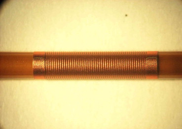
Microcoil Fabrication
Get Radiology Tree app to read full this article<
Get Radiology Tree app to read full this article<
In Vitro Experimental Design
Get Radiology Tree app to read full this article<
Get Radiology Tree app to read full this article<
Get Radiology Tree app to read full this article<
Get Radiology Tree app to read full this article<
Get Radiology Tree app to read full this article<
Get Radiology Tree app to read full this article<
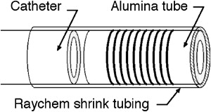
Microcoil-catheter Construction
Get Radiology Tree app to read full this article<
Get Radiology Tree app to read full this article<
Get Radiology Tree app to read full this article<
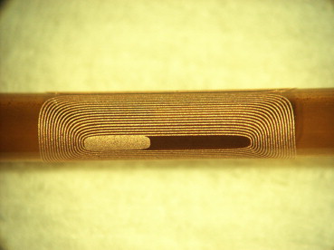
Then, 0.0508-mm (0.002-inch) wire was soldered to the 0.127-mm wire at the catheter tip and was fed through holes that had been drilled in the polyimide tube near the coil connection pads. The 0.0508-mm wires were then soldered to the coil connection pads. The microcoil assembly was next glued to the tip of the microcatheter and secured with heat-shrinkable tubing (Raychem, North Spring, TX). In the case of the microcoil on alumina, the heat-shrinkable tubing covered all but the distal end of the microcoil assembly, while in the case of the microcoil on polyimide, it covered only the proximal end of the microcoil assembly, leaving the microcoil in direct contact the surrounding fluid. The 0.127-mm copper wires at the microcatheter hub were connected to a five-pin or eight-pin electrical connector (a male telephone or Ethernet jack). The jack was plugged into a female connector on an electrical switch box (used to change the electrical polarity of the direct currents), which was connected to up to three direct current power supplies.
Get Radiology Tree app to read full this article<
Get Radiology Tree app to read full this article<
Catheter Preparation for in Vivo Testing
Get Radiology Tree app to read full this article<
In Vivo Testing at 1.5 T
Get Radiology Tree app to read full this article<
Get Radiology Tree app to read full this article<
Get Radiology Tree app to read full this article<
In Vivo Imaging and Heating Experiments
Get Radiology Tree app to read full this article<
Table 1
Gross and Histologic Findings in Porcine CCAs After Testing of Alumina-tipped Microcatheters With Various Durations of bFFE Imaging and Microcoil Current Application
Current to Microcoils (mA) Duration of Current to Microcoils (seconds) Duration of bFFE Imaging (seconds) Gross and Histologic Findings Left CCA: normal arterial flow 300 30 30 No thrombus, no damage to arterial wall 300 60 60 No thrombus, no damage to arterial wall 300 300 300 No thrombus, no damage to arterial wall 0 0 30 No thrombus, no damage to arterial wall 0 0 60 No thrombus, minimal medial vacuolization likely within normal limits 0 0 300 No thrombus, poorly preserved specimen limits histologic evaluation Right CCA: zero arterial flow 300 30 30 No thrombus, no damage to arterial wall 300 60 60 No thrombus, no damage to arterial wall 300 300 300 No thrombus, no damage to arterial wall 0 0 30 Platelet and fibrin thrombus adjacent to endothelium, no damage to arterial wall 0 0 60 Platelet and fibrin thrombus adjacent to endothelium, no damage to arterial wall 0 0 300 Platelet and fibrin thrombus detached from endothelium, no damage to arterial wall
bFFE, balanced fast field echo; CCA, common carotid artery.
Get Radiology Tree app to read full this article<
Euthanasia and Postmortem Gross and Histologic Analyses
Get Radiology Tree app to read full this article<
Results
Get Radiology Tree app to read full this article<
Get Radiology Tree app to read full this article<
Get Radiology Tree app to read full this article<
Get Radiology Tree app to read full this article<
Get Radiology Tree app to read full this article<
Discussion
Get Radiology Tree app to read full this article<
J=−κ⋅gradTbecomesJ=1/lπd=κΔT/x, J
=
−
κ
⋅
grad
T
becomes
J
=
1
/
l
π
d
=
κ
Δ
T
/
x
,
where the heat flux, J (W/m 2 ), is 1 W divided by the surface area of the microcoil, l π d , and grad T is the temperature difference between the outer (hotter) and inner (cooler) tube surfaces, Δ T , divided by the tube wall thickness, x . Δ T is the only unknown in this equation.
Get Radiology Tree app to read full this article<
Get Radiology Tree app to read full this article<
Get Radiology Tree app to read full this article<
Get Radiology Tree app to read full this article<
Get Radiology Tree app to read full this article<
Get Radiology Tree app to read full this article<
Get Radiology Tree app to read full this article<
Get Radiology Tree app to read full this article<
Get Radiology Tree app to read full this article<
Conclusions
Get Radiology Tree app to read full this article<
Get Radiology Tree app to read full this article<
References
1. Roberts T.P., Hassenzahl W.V., Hetts S.W., et. al.: Remote control of catheter tip deflection: an opportunity for interventional MRI. Magn Reson Med 2002; 48: pp. 1091-1095.
2. Settecase F., Sussman M.S., Wilson M.W., et. al.: Magnetically-assisted remote control (MARC) steering of endovascular catheters for interventional MRI: a model for deflection and design implications. Med Phys 2007; 34: pp. 3135-3142.
3. Athey T.W.: Current FDA guidance for MR patient exposure and considerations for the future. Ann N Y Acad Sci 1992; 649: pp. 242-257.
4. Yeung C.J., Susil R.C., Atalar E.: RF heating due to conductive wires during MRI depends on the phase distribution of the transmit field. Magn Reson Med 2002; 48: pp. 1096-1098.
5. Yeung C.J., Atalar E.: RF transmit power limit for the barewire loopless catheter antenna. J Magn Reson Imaging 2000; 12: pp. 86-91.
6. Qiu B., Yeung C.J., Du X., et. al.: Development of an intravascular heating source using an MR imaging guidewire. J Magn Reson Imaging 2002; 16: pp. 716-720.
7. Shellock F.G.: Radiofrequency energy-induced heating during MR procedures: a review. J Magn Reson Imaging 2000; 12: pp. 30-36.
8. Shellock F.G.: Magnetic resonance safety update 2002: implants and devices. J Magn Reson Imaging 2002; 16: pp. 485-496.
9. Nitz W.R., Oppelt A., Renz W., et. al.: On the heating of linear conductive structures as guide wires and catheters in interventional MRI. J Magn Reson Imaging 2001; 13: pp. 105-114.
10. Konings M.K., Bartels L.W., Smits H.F., et. al.: Heating around intravascular guidewires by resonating RF waves. J Magn Reson Imaging 2000; 12: pp. 79-85.
11. Dempsey M.F., Condon B., Hadley D.M.: Investigation of the factors responsible for burns during MRI. J Magn Reson Imaging 2001; 13: pp. 627-631.
12. Balaris C.: Antenna theory: analysis and design.1982.John WileyNew York
13. Ladd ME, Quick HH, Boesiger P, et al. RF heating of actively visualized catheters and guidewires. Presented at: ISMRM 6th Scientific Meeting and Exhibition; Sydney, Australia; April 1998.
14. Settecase F, Sussman MS, Wilson MW, et al. Evaluation of RF and resistive heating due to magnetically-assisted remote control (MARC) steering coils for endovascular interventional MRI. Presented at: 16th Annual Meeting of the ISMRM; Toronto, ON, Canada; 2008.
15. Settecase F., Hetts S.W., Martin A.J., et. al.: RF heating of MRI-assisted catheter steering coils for interventional MRI. Acad Radiol 2011; 18: pp. 277-285.
16. Center for Devices and Radiological Health: Guidance for the submission of premarket notifications for magnetic resonance diagnostic devices.1998.US Food and Drug AdministrationRockville, MD 21
17. International Electrotechnical Commission: International standard, medical equipment—part 2: particular requirements for the safety of magnetic resonance equipment for medical diagnosis.2nd rev ed2002.International Electrotechnical CommissionGeneva, Switzerland
18. Malba V., Maxwell R., Evans L.B., et. al.: Laser-lathe lithography—a novel method for manufacturing nuclear magnetic resonance microcoils. Biomed Microdev 2003; 5: pp. 21.
19. Lide D.R.CRC handbook of chemistry and physics.2005.CRC PressBoca Raton, FL: