
Rationale and Objectives
There has been a trend toward lowering tube potential in computed tomography angiography (CTA) examinations to reduce radiation dose or contrast medium dose. The aim of this study was to evaluate the influence of tube potential on peripheral artery in-stent lumen visibility in CTA examinations.
Materials and Methods
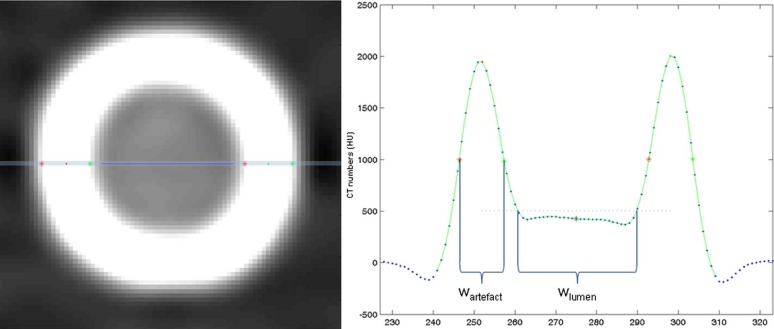
Nine different peripheral artery stents were placed in a vessel phantom (inner diameter: 5 mm, surrounded by water) and scanned consecutively using a 128-row CT scanner with 70, 80, 100, 120, and 140 kV and two different concentrations of contrast medium to simulate contrast-enhanced blood. Medium-smooth and ultra-sharp reconstruction kernels with filtered back projection (B30f, B46f) and iterative reconstruction technique (I30f, I46f) were used. Visible in-stent lumen diameter and artifact width were evaluated using a semiautomatic software tool. All stents were scanned with digital angiography, which was regarded as the reference standard.
Results
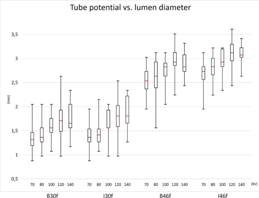
Averaged over all stents, visible in-stent lumen diameter ranged from 1.30 ± 0.21 mm (CM2/70 kV/I30f) to 3.13 ± 0.32 mm (CM1/120 kV/I46f). In-stent lumen diameters were significantly higher for 120 and 140 kV compared to 70 kV (2.39 ± 0.73 and 2.39 ± 0.66 mm vs 1.99 ± 0.69 mm; P = 0.01 and P = 0.005). Ultra-sharp reconstruction kernels lead to significantly better in-stent lumen visibility than smooth reconstruction kernels (B46f: 2.74 ± 0.34 mm vs B30f: 1.57 ± 0.36 mm; P < 0.001, respectively). Furthermore, in-stent lumen visibility was improved for iterative reconstructions compared to filtered back projection (I46f: 2.93 ± 0.30 mm vs B46f: 2.74 ± 0.34 mm; P < 0.001). Contrast medium concentration did not influence in-stent lumen visibility.
Conclusions
Despite all known benefits of low kV CTA protocols, the use of a very low tube potential may hamper in-stent lumen visibility. A sharp kernel may be of value when evaluating the inner lumen of vascular stents.
Introduction
Stent-assisted angioplasty is commonly performed in peripheral and visceral artery stenosis or occlusions . Restenosis after stent implementation may occur because of intimal hyperplasia . Furthermore, stent thrombosis may occur. Therefore, evaluation of in-stent lumen can be of significant importance in patients following stent implementation. In clinical routine, three noninvasive methods may be used to evaluate the vascular status of the peripheral arteries: duplex ultrasound, magnetic resonance angiography, and computed tomography angiography (CTA).
Duplex ultrasound is widely available and leads to a good vascular assessment but suffers from a relevant interobserver variability . Furthermore, not all anatomic regions can be assessed using duplex ultrasound. Magnetic resonance angiography allows excellent peripheral vascular assessment, but in the presence of metallic stents magnetic field inhomogeneities might cause pseudo-stenoses or pseudo-obstructions . Multidetector single-energy CTA is routinely performed for assessment of peripheral and visceral arteries, and provides high sensitivity and specificity for assessment of vascular stenoses .
Get Radiology Tree app to read full this article<
Get Radiology Tree app to read full this article<
Get Radiology Tree app to read full this article<
Materials and Methods
Study Setup
Stents and Phantom Setup
Get Radiology Tree app to read full this article<
Table 1
Stent Specifications
Name Manufacturer D nom (mm) Type (B/S) Material D xray (mm) D CT (mm) W CT (mm) LifeStent Edwards Lifescience 6 S Nitinol 4.6 2.45 ± 0.69 1.41 ± 0.30 Palmaz Genesis Cordis 5 B Steel 4.3 2.06 ± 0.66 1.46 ± 0.34 Easy Wallstent Schneider 6 S Cobalt-based alloy 4.4 2.27 ± 0.71 1.37 ± 0.26 Visi-Pro EV3 6 B Steel 4.3 2.13 ± 0.68 1.38 ± 0.26 Herculink Elite Abbott 5 B Cobalt-chromium alloy 3.9 1.72 ± 0.67 1.38 ± 0.27 Absolute Pro Abbott 6 S Nitinol 4.5 2.36 ± 0.68 1.42 ± 0.30 Omnilink Elite Abbott 6 B Cobalt-chromium alloy 4.3 2.04 ± 0.70 1.36 ± 0.25 Xpert Abbott 5 S Nitinol 4.7 2.61 ± 0.56 1.74 ± 0.48 sinus SuperFlex Optimed 7 S Nitinol 4.7 2.32 ± 0.69 1.39 ± 0.26
B, balloon-expandable; CT, computed tomography; D CT , inner stent diameter after deployment in tube as measured by CT, averaged over all scan settings; D nom , nominal diameter given by the manufacturer; D xray , inner stent diameter after deployment in tube as measured using x-ray (reference standard); S, self-expandable; W CT , apparent stent width after deployment in tube as measured by CT, averaged over all scan settings.
Get Radiology Tree app to read full this article<
Establishment of Reference Standard
Get Radiology Tree app to read full this article<
CT Scanning Parameters and Image Reconstruction
Get Radiology Tree app to read full this article<
Image Analysis
Get Radiology Tree app to read full this article<
Get Radiology Tree app to read full this article<
Get Radiology Tree app to read full this article<
Statistical Analysis
Get Radiology Tree app to read full this article<
Results
In-stent Lumen Visibility
Get Radiology Tree app to read full this article<
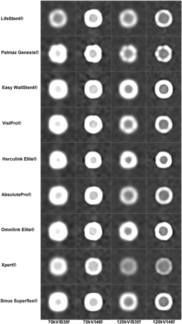
Table 2
In-stent Lumen Visibility and Apparent Stent Width for the Different Tube Potentials, Reconstruction Kernels, and Contrast Medium Concentrations Averaged Over All Stents
In-stent Lumen (mm) Apparent Stent Width (mm) Tube Potential (kV) Kernel CM1 CM2 CM1 CM2 70 B30f 1.41 ± 0.34 1.30 ± 0.21 2.02 ± 0.21 1.64 ± 0.13 B46f 2.59 + 0.32 2.51 ± 0.29 1.32 ± 0.15 1.15 ± 0.04 I30f 1.36 ± 0.27 1.40 ± 0.31 2.05 ± 0.20 1.66 ± 0.09 I46f 2.65 ± 0.32 2.73 ± 0.24 1.39 ± 0.08 1.23 ± 0.02 80 B30f 1.44 ± 0.32 1.42 ± 0.29 1.87 ± 0.28 1.57 ± 0.10 B46f 2.69 ± 0.30 2.53 ± 0.48 1.23 ± 0.16 1.10 ± 0.04 I30f 1.44 ± 0.33 1.48 ± 0.33 1.86 ± 0.17 1.59 ± 0.08 I46f 2.79 ± 0.28 2.83 ± 0.24 1.29 ± 0.07 1.17 ± 0.02 100 B30f 1.55 ± 0.22 1.63 ± 0.33 1.79 ± 0.28 1.53 ± 0.15 B46f 2.73 ± 0.24 2.73 ± 0.32 1.19 ± 0.16 1.07 ± 0.06 I30f 1.57 ± 0.29 1.73 ± 0.32 1.80 ± 0.26 1.54 ± 0.10 I46f 2.90 ± 0.25 2.99 ± 0.25 1.21 ± 0.11 1.11 ± 0.02 120 B30f 1.77 ± 0.45 1.70 ± 0.43 1.76 ± 0.27 1.52 ± 0.15 B46f 2.99 ± 0.33 2.89 ± 0.33 1.15 ± 0.13 1.05 ± 0.03 I30f 1.80 ± 0.43 1.76 ± 0.38 1.74 ± 0.23 1.54 ± 0.13 I46f 3.13 ± 0.32 3.08 ± 0.31 1.16 ± 0.08 1.09 ± 0.03 140 B30f 1.75 ± 0.37 1.76 ± 0.36 1.74 ± 0.27 1.53 ± 0.18 B46f 2.88 ± 0.21 2.89 ± 0.27 1.17 ± 0.17 1.07 ± 0.10 I30f 1.84 ± 0.35 1.88 ± 0.35 1.71 ± 0.20 1.53 ± 0.10 I46f 3.08 ± 0.21 3.08 ± 0.20 1.14 ± 0.07 1.10 ± 0.05
CM1, contrast medium dilution 1 (300 HU at 120 kV); CM2, contrast medium dilution 2 (300 HU at 70 kV); B30f, B46f, I30f, and I46f, reconstruction kernels; kV, kilovoltage.
Get Radiology Tree app to read full this article<
Impact of Tube Potential
Get Radiology Tree app to read full this article<
Get Radiology Tree app to read full this article<
Impact of Reconstruction Kernel
Get Radiology Tree app to read full this article<
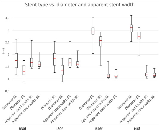
Impact of Stent Material
Get Radiology Tree app to read full this article<
Table 3
Apparent Stent Width and In-stent Lumen Diameter for Self-expandable and Balloon-expandable Stents
Apparent Stent Width (mm) Lumen Diameter (mm) Self-expandable Balloon-expandable_P_ -value Self-expandable Balloon-expandable_P_ -value All 1.47 ± 0.36 1.40 ± 0.28 0.25 2.40 ± 0.67 1.99 ± 0.69 <0.001 B30f 1.75 ± 0.30 1.63 ± 0.17 0.15 1.77 ± 0.34 1.33 ± 0.23 <0.001 B46f 1.17 ± 0.17 1.13 ± 0.08 0.52 2.92 ± 0.26 2.52 ± 0.30 <0.001 I30f 1.74 ± 0.26 1.65 ± 0.17 0.32 1.83 ± 0.32 1.38 ± 0.26 <0.001 I46f 1.20 ± 0.11 1.18 ± 0.09 0.99 3.09 ± 0.21 2.72 ± 0.25 <0.001
B30f, B46f, I30f, and I46f, reconstruction kernels.
Get Radiology Tree app to read full this article<
Impact of Contrast Medium Concentration
Get Radiology Tree app to read full this article<
Apparent Stent Width
Get Radiology Tree app to read full this article<
Attenuation and Image Noise
Get Radiology Tree app to read full this article<
Get Radiology Tree app to read full this article<
Get Radiology Tree app to read full this article<
Discussion
Get Radiology Tree app to read full this article<
Get Radiology Tree app to read full this article<
Get Radiology Tree app to read full this article<
Get Radiology Tree app to read full this article<
Get Radiology Tree app to read full this article<
Get Radiology Tree app to read full this article<
Get Radiology Tree app to read full this article<
Conclusions
Get Radiology Tree app to read full this article<
Get Radiology Tree app to read full this article<
References
1. Hirsch A.T., Haskal Z.J., Hertzer N.R., et. al.: ACC/AHA Guidelines for the Management of Patients with Peripheral Arterial Disease (lower extremity, renal, mesenteric, and abdominal aortic): a collaborative report from the American Associations for Vascular Surgery/Society for Vascular Surgery, Society for Cardiovascular Angiography and Interventions, Society for Vascular Medicine and Biology, Society of Interventional Radiology, and the ACC/AHA Task Force on Practice Guidelines (writing committee to develop guidelines for the management of patients with peripheral arterial disease)—summary of recommendation. J Vasc Interv Radiol 2006; 17: pp. 1383-1397.
2. Sabeti S., Schillinger M., Amighi J., et. al.: Primary patency of femoropopliteal arteries treated with nitinol versus stainless steel self-expanding stents: propensity score-adjusted analysis. Radiology 2004; 232: pp. 516-521.
3. Kaempf M., Ketelsen D., Syha R., et. al.: CT angiography of various superficial femoral artery stents: an in vitro phantom study. Eur J Radiol 2012; 81: pp. 1584-1588.
4. Krnic A., Vucic N., Sucic Z.: Duplex scanning compared with intra-arterial angiography in diagnosing peripheral arterial disease: three analytical approaches. Vasa 2006; 35: pp. 86-91.
5. Morvay Z., Nagy E., Bagi R., et. al.: Sonographic follow-up after visceral artery stenting. J Ultrasound Med 2004; 23: pp. 1057-1064.
6. Agid R., Schaaf M., Farb R.: CE-MRA for follow-up of aneurysms post stent-assisted coiling. Interv Neuroradiol 2012; 18: pp. 275-283.
7. Schernthaner R., Stadler A., Lomoschitz F., et. al.: Multidetector CT angiography in the assessment of peripheral arterial occlusive disease: accuracy in detecting the severity, number, and length of stenoses. Eur Radiol 2008; 18: pp. 665-671.
8. Martin M.L., Tay K.H., Flak B., et. al.: Multidetector CT angiography of the aortoiliac system and lower extremities: a prospective comparison with digital subtraction angiography. Am J Roentgenol 2003; 180: pp. 1085-1091.
9. Romano M., Amato B., Markabaoui K., et. al.: Multidetector row computed tomographic angiography of the abdominal aorta and lower limbs arteries. A new diagnostic tool in patients with peripheral arterial occlusive disease. Minerva Cardioangiol 2004; 52: pp. 9-17. English, Italian
10. Megyeri B., Christe A., Schindera S.T., et. al.: Diagnostic confidence and image quality of CT pulmonary angiography at 100 kVp in overweight and obese patients. Clin Radiol 2015; 70: pp. 54-61.
11. Qi L., Zhao Y., Zhou C.S., et. al.: Image quality and radiation dose of lower extremity CT angiography at 70 kVp on an integrated circuit detector dual-source computed tomography. Acta Radiol 2015; 56: pp. 659-665.
12. Iezzi R., Cotroneo A.R., Giammarino A., et. al.: Low-dose multidetector-row CT-angiography of abdominal aortic aneurysm after endovascular repair. Eur J Radiol 2011; 79: pp. 21-28.
13. Oca Pernas R., Delgado Sánchez-Gracián C., Tardáguila de la Fuente G., et. al.: Comparison of image quality and radiation dose in computed tomography angiography of the peripheral arteries using tube voltage of 80 kV versus 100 kV. Radiologia 2014; 56: pp. 541-547.
14. Sirineni G.K., Kalra M.K., Pottala K., et. al.: Effect of contrast concentration, tube potential and reconstruction kernels on MDCT evaluation of coronary stents: an in vitro study. Int J Cardiovasc Imaging 2007; 23: pp. 253-263.
15. Nieman K., Cademartiri F., Raaijmakers R., et. al.: Noninvasive angiographic evaluation of coronary stents with multi-slice spiral computed tomography. Herz 2003; 28: pp. 136-142.
16. Köhler M., Burg M.C., Bunck A.C., et. al.: Angiography of peripheral arterial stents: in vitro evaluation of 22 different stent types. Radiol Res Pract 2011; 2011: pp. 103873.
17. Lee Y.J., Lim Y.S., Jung N.Y., et. al.: In vivo evaluation of carotid artery stents using multi-detector-row computed tomography angiography: comparison of 3 kernels. J Comput Assist Tomogr 2013; 37: pp. 402-407.
18. Heuschmid M., Wiesinger B., Tepe G., et. al.: Evaluation of various image reconstruction parameters in lower extremity stents using multidetector-row CT angiography: initial findings. Eur Radiol 2007; 17: pp. 265-271.
19. Gassenmaier T., Petri N., Allmendinger T., et. al.: Next generation coronary CT angiography: in vitro evaluation of 27 coronary stents. Eur Radiol 2014; 24: pp. 2953-2961.
20. Ebersberger U., Tricarico F., Schoepf U.J., et. al.: CT evaluation of coronary artery stents with iterative image reconstruction: improvements in image quality and potential for radiation dose reduction. Eur Radiol 2013; 23: pp. 125-132.